|
||||
|
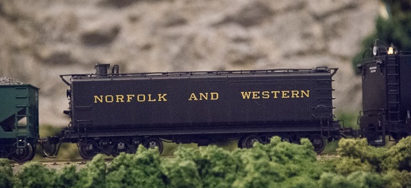
BLI Aux. Water Tender
Auxillary water tender (aka a canteen or water bottle) The Broadway Limited Imports N&W auxillary water tender is another finely crafted model by BLI. When used on DCC out of the box, both lights on the tender light simultaneously. Installing a function-only decoder allows you to control both of the lights indendently. If you want, you can MU the tender with your engine. The first challenge is getting it open. The shell can be pried from the chassis in the corners. It is a tight fit. To be honest, you will be risking damaging the shell or chassis. So pry with something that has a broad tip to spread out the pressure.
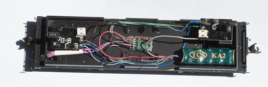
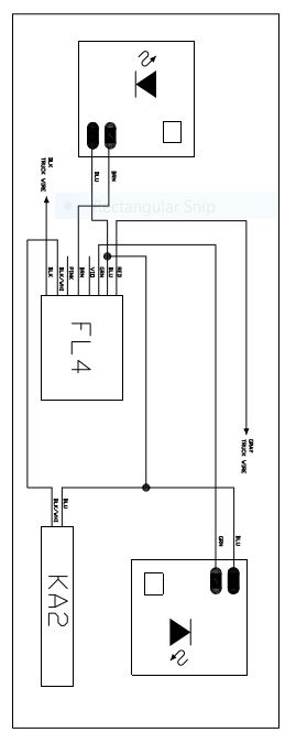
Thanks to Ken Klaviter for getting the shell off and doing the wiring of this auxillary water tender! I used a TCS four function-only decoder. I also used the TCS keep alive module because the tender has limited power pick-up and will flicker without the keep alive module. The keep alive module costs more than the decoder. You may want to wire your model without the keep alive module and see how bad it flickers before spending the money. You don't have to use a TCS decoder, but whatever brand you choose, make sure you use one that supports a keep alive module in case you need it. If you want, you can use a typical motor decoder and just don't hook up the motor outputs to anything. You will be using the BLI circuit boards that hold the LEDs in position. As such, you will also be using the resistors on the circuit boards that are always needed when using LED lights. Using the BLI resistors, you will not need to add any of your own. You will no longer be using the BLI connectors. My model is wired with the function decoder's wires directly to solder pads on the BLI circuit boards. If you feel your soldering skills may damage the BLI circuit boards, you can leave the existing wires attached to the circuit boards and then solder the decoder wires to them.
Modelers frequently assign the locomotive number as the address for the decoder. But here, you will have a few challenges. For starters, N&W didn't use large numbers so the scale numbers on the tender are TINY. Even under my magnifying light, they are next to impossible to read. Second, DCC only supports addresses up to about 10,000 and the N&W has more digits than that. So you will have to assign an arbitrary number to your function decoder. I bought two auxillary water tenders, so I needed a way to tell them apart since the existing numbers are too small to read. I'm told the prototype marked cars with chalk when switching them. So with a fine-point, white felt pen or a fine tip paint brush, we put small, vertical strokes on the ends of the tender. One tender has one stroke and the other has two. To give you independent control of the lights as well as directional control should you MU the tender with the locomotive, program the CVs as follows: CV 51 (green wire): 16 One of the tender headlights is centered and the other is offset. I'm not certain which way the prototype used the tender. I assumed the offset light faced forward so as to not blind the engine crew had the centered light been facing forward. If I'm wrong and you know better, please let me know. In any event, if you want to change how the tender is used directionally, you can swap the above values for the two CVs. Enjoy your new tender! |
Copyright by Allan Gartner 1996 - 2016 © All rights reserved. You may print this for your own, personal, non-commercial use. Non-commercial, non-personal reproduction may be requested by visiting www.WiringForDCC.com/writeme.htm . All users, commercial and non-commercial, may link only to this site at www.WiringForDCC.com. Thanks to all who contribute to this site and the Q&A forum! |