Bus Tests
Twisted vs. Untwisted
RC Filter
Buses Tied Together
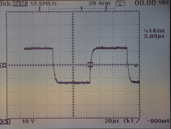
I intend to start off with one of the scope traces and explain what is being displayed.
A "1" half bit is 55 - 61 µS wide. 58 µSec is nominal.
A "0" half bit is 95 - 9900 µSec wide. 100 µSec is nominal.
NMRA Electrical Standard

This page under construction!
Link to Intro
Link to NCE
Link to NCE Conclusion
Link to Digitrax
Link to Digitrax Conclusion

NCE
(Output of PB105 Booster)
Does Twisting The Bus Help?

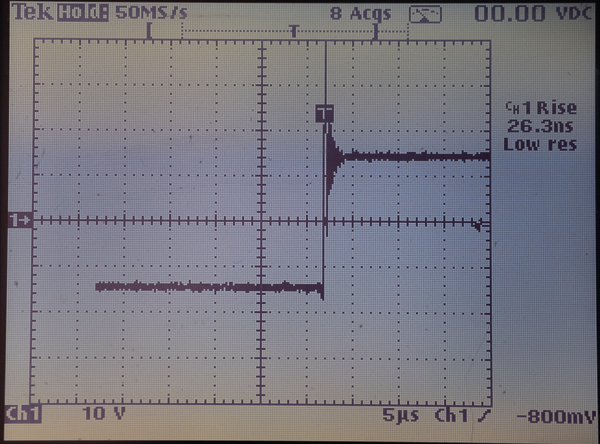
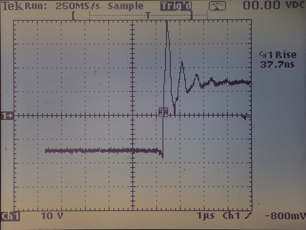
Example N1: Measurement taken at end of 47 foot, untwisted bus. Driven by NCE PB105.
Note spike to 40V and ringing.
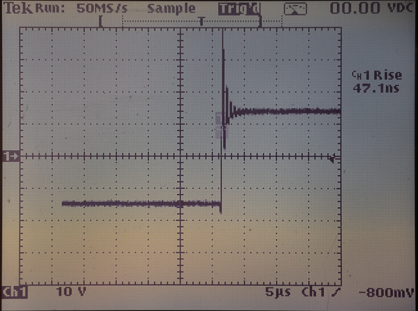
Example N5: Measurement taken at end of 47 foot, twisted bus, driven by a NCE PB105. There is no load on the bus.
The bus is twisted with about 3-5 turns per foot. (More at the end that the drill was attached to.) Ringing is still peaking at about 40V.
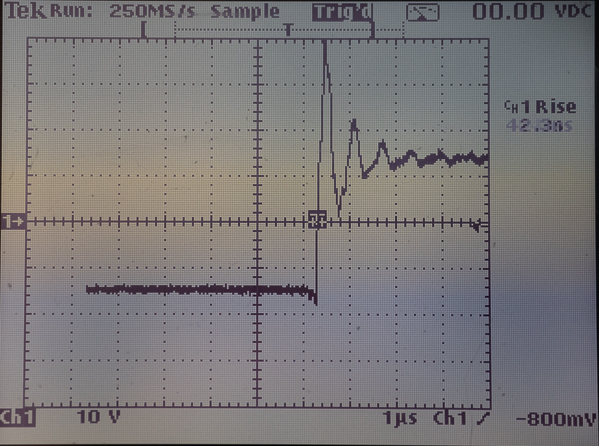
Example N6: Measurement taken at end of 47 foot, twisted bus with no load. Driven by a NCE PB105. Sweep speed increased so that spike and ringing is more observable.
The bus is twisted with about 3-5 turns per foot. (More at the end that the drill was attached to.) Ringing is still peaking at about 40V. The above traces do not seem to support the idea that twisting the bus helps when the bus is not loaded. Of course, when you have one or more locomotives operating on your layout, that is a load.
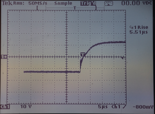
Example N2: Measurement taken at end of 47 foot, untwisted bus with a taillight load. Driven by a NCE PB105.
The taillight is loading the signal down and dampening out the spike and ringing. If you look carefully, you can see evidence of the dampened ringing just below the "T".
Example N7: Measurement taken at end of 47 feet of twisted bus with a taillight load. Driven by a NCE PB105.
Apparent conclusion: Twisting makes no difference.
Does RC Filter (Snubber) Help? Does it Hurt?
Example N2: Measurement taken at end of 47 foot, untwisted bus with a taillight load. Driven by a NCE PB105.
The taillight is loading the signal down and dampening out the spike and ringing. If you look carefully, you can see evidence of the dampened ringing just below the "T".
Example N3: Same conditions as above (at end of 47 feet, untwisted bus, light bulb load) but with the sweep speed reduced so that you can see moe of the waveform.
Example N4: Measurement taken at end of 47 feet with a taillight load and untwisted bus. Driven by a PB105. Includes an RC filter.
Notice that small amount of ringing is gone. The waveform is otherwise unchanged.
Example N14: Measurement taken at 47 feet, twisted bus, no load, with NCE RC filter (snubber). Driven by NCE PB105.
Slight rounding of leading edge; not enough to corrupt DCC data bit.
Example N7: Measurement taken at end of 47 feet of twisted bus with a taillight load. Driven by a NCE PB105.
There is evidence of ringing on the leading edge, but mostly, the waveform is being dampened by the taillight.
Example N9: Measurement taken at end of 47 feet of twisted bus with no load. Driven by NCE PB105.
Ringing is reaching to 40V that could potentially damage decoders.
Example N16: Measurement taken at 47 feet, untwisted bus, no load, with NCE RC filter (snubber). Driven by a NCE PB105.
Note lack of ringing and spike. Slight rounding of leading edge at top. This is not significant.
Example N18: Measurement taken at 47 feet, untwisted bus, no load, with NCE RC filter(snubber). Driven by NCE PB105.
Spike and ringing reduced with RC filter. Slight damping of leading edge, but not enough to corrupt the DCC data bit.
Apparent conclusion: RC Filter (snubber) helps reduce ringing and spikes without adverse affect to the DCC waveform.
This test wil be rerun for Digitrax equipment once I am done with the NCE tests.
If two bus ends are tied together, is that a problem?
Example N11: Measurement taken at 47 feet with a taillight load and a NCE RC filter (snubber). Bus consist of 47 feet of untwisted and 47 feet of twisted tied together at end. Driven by a NCE PB105.
Example N12: Same as N11, but different sweep speed showing more of the waveform.
Apparent conclusion: Tying bus ends together does not cause a problem.
Is an interruption in track power a concern?
Ignore channel 2 in the following traces. It is being used simply to trigger the test equipment. Channel 1 is the DCC signal.
Note also that scope does not have a 1x input even though a 1x probe was used. There is nothing about 100V about this signal. A 9V battery was used to trigger. I am wondering why the trigger signal is not cleaner.
Will attempt to interrupt power, rather than simply apply it, as was done here.
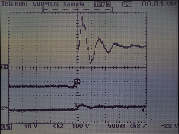
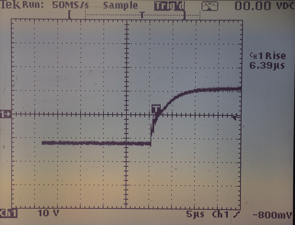
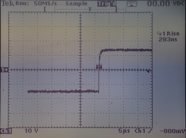
Example N19: Measurement taken at 47 feet, untwisted bus, with no load, no filter.
Turn-on spike test. Spike reaches almost 40V. Could damage decoder.
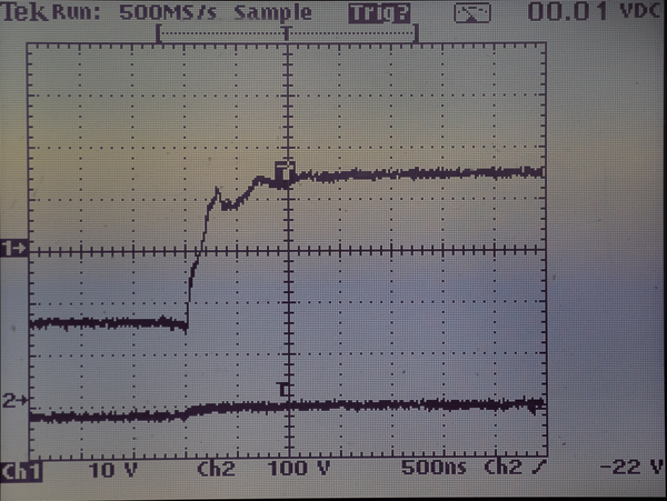
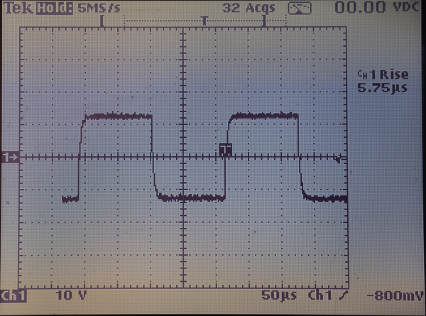
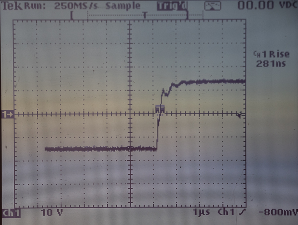
Example N20: Measurement taken at 47 feet, untwisted bus, no load, with NCE RC filter (snubber). Driven by NCE PB105.
Shows that RC filter (snubber) helps suppress start up spikes.
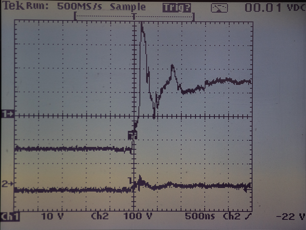
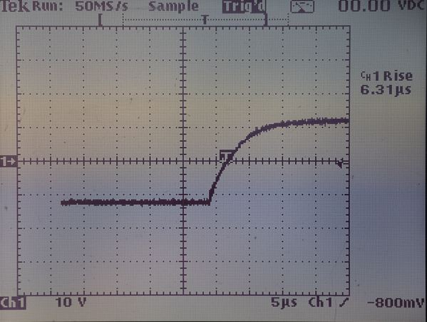
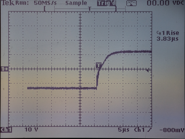
Example N22: Measurement taken at 47 feet, twisted bus with no load, no filter. Driven by NCE PB105. Turn-on spike test.
Apparent conclusion: RC filter (snubber) helps reduce spike and ringing at turn-on.
Will attempt to run a try track power interruption test. May not be able to capture entire event in one sweep due to sweep speed that may need to be used.
TRACES THAT MAY NOT BE NEEDED

Example N8: Measurement taken at 47 feet of untwisted bus with a lightbulb load. Driven by an NCE PB105. Note ringing. THIS CAN'T BE RIGHT. Did load come disconnected?

Example N10: Measurement taken at 47 feet of a twisted bus with no load. Driven by a NCE PB105. THIS DOESN'T SEEM RIGHT EITHER.

Example N15: LOOK IN LR.

Example N13: This test was run before. Measurement taken at 47 feet of twisted bus with no RC filter and no load. Driven by NCE PB105. DON'T NEED THIS ONE.

Example N17: Measurement taken at 47 feet, untwisted bus, no filter, no load. Compare to previous shot with filter, untwisted. THIS MAY NOT BE NEEDED.

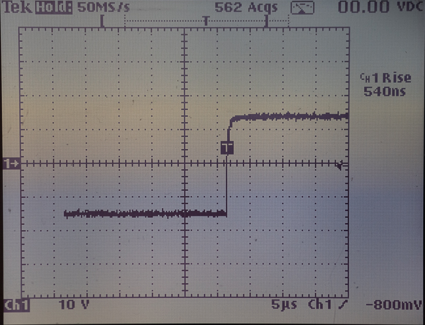
Example N21: Measurement taken at 47 feet, untwisted bus, no load. Driven by NCE PB105, Filter??? Spike test.

Example N23: Measurement taken at 47 feet, twisted bus, no load, no filter. Driven by NCE PB105. Spike test. Acts like filter in was in place.

Example N25: Measurement taken at 47 feet, twisted bus, with taillight load and NCE RC filter (snubber). Spike test.
Digitrax
(Output DCS210 Command Station/Booster)

Output of DCS210 with no bus attached.

Signal at DCS210 driving 47 foot untwisted bus. No load or RC filter.

Signal at DCS210 driving 47 foot untwisted bus with 1156 bulb load and NCE RC filter at end.

Signal at 30 feet of 47 footuntwisted bus driven by DCS210 with a 1156 bulb load at end. No RC filter.

Signal at 30 feet of 47 foot untwisted bus. Driven by DCS210 with a 1156 bulb load and NCE RC filter at end.

Signal at end of 47 foot untwisted bus driven by DCS210 with 1156 bulb load. No RC filter.

Signal at end of 47 feet of untwisted bus. Driven by DCS210 with 1156 bulb load and NCE RC filter.

Signal at DCS210 with twisted 47 foot bus attached. No load.

Signal at end of 47 foot twisted bus. Driven by DCS210. 1156 bulb load at end.

Signal at 30 feet of 47 foot twisted bus. Driven by DCS210. 1156 bulb load at end.

Signal at 30 feet of 47 foot twisted bus. Driven by DCS210. 1156 bulb load and NCE RC filter at end.

Signal at 47 feet of 47 foot twisted bus. Driven by DCS210 with 1156 bulb load at end.

Signal at end of 47 feet of 47 foot twisted bus. Driven by DCS210 with 1156 bulb load and NCE RC filter at end.
Conclusion:
RC filter: Does it degrade Digitrax signal?
