|
||||
|
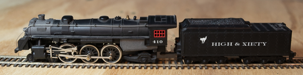
HO Mantua Pacific or Mikado using a Decoder Buddy
Introduction Mantua has several locomotives that are not materially different from each other. Their Pacific and Mikado are two such locomotives. The tenders are the same and the boilers appear to be the same. Only the wheel arrangements on the locomotive are different. So this installation applies equally to both locomotives. Mantua locomotives have quite a history. Depending on the vintage of Mantua locomotive you have, it will either have an open-frame motor or a can motor. As is typically the case, the can motor is better. If you have an open frame motor, note that the motor has one of the wipers connected to the chassis. YOU MUST REMOVE THIS CONNECTION OR YOU WILL LET THE SMOKE OUT OF YOUR DECODER AND IT WILL BE RUINED. Unfortunately, I don't have a picture of one of the open frame motors to show you at this time. I will include one in the future if I find one. As you well know, a quality canned motor is preferred. Most of my "good" locomotives now have decoders in them. Many modern locomotives either come with DCC or easily accomodate snapping in a decoder. I've also been busy with a job, so I haven't had the need or time to install a decoder in a long time. When NixTrainz https://nixtrainz.com contacted me about looking at their Decoder Buddy, this was a good time to plug in the soldering iron and check it out and a Soundtraxx Tsunami2 21-pin sound decoder. This was a fairly straightforward installation, so this is more about my thoughts on the Decoder Buddy and the Soundtraxx 21-pin sound decoder than anything else. So if you want to use either of these products, read on. Decoder Buddy
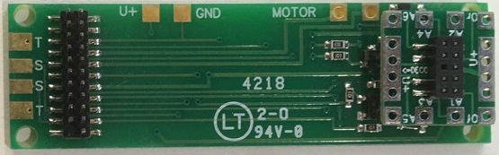
Decoder Buddy Decoder Buddy is intended to make easy installation of 21-pin decoders in locomotives that do not already have sockets for these decoders. The NixTrainz website contains more pictures and installation instructions that I will not duplicate here. Here are my thoughts and observations. It consists of a mother board, shown above, that is well-suited for installations in diesels. It contains connections for the track (T), speaker (S), a keep-alive circuit (U+ and GND), and the motor. To the right as shown above, is a daughter board. It contains connections for the headlights and other functions. These are located on the daughter board so that headlights, cab lights, marker, number boards, and ditchlights can be a part of the locomotive shell. You can remove the shell and set it aside when you disconnect the daughter board should you need to. In doing a steam locomotive, there are times that you might wish that some of the function solder pads were actually on the mother board. If you mount your speaker under a coal load, you might want the speaker connections on the daughter board. I realized that every situation is different and that having all connections on the daughter or mother board would make both bigger. You can't have everything! At least with the speaker, NixTrainz can add a connector to the mother board for you. Now is a good time to take note of the orientation on the daughter board. Note the connector that connects it to the mother board is on the top of the daughter board and that the pins from the mother board go through the bottom of the daughter board. The purpose of the Decoder Buddy is to make installation of a 21-pin decoder easier. It has built in 2.2k-ohm resistors for driving LEDs. Different resistor values or no resistor at all are available upon request from NixTrainz. The daughter board has several holes to solder wires for lights and other functions. You don't have to run a number of splices to the function common blue wire. For a steam locomotive with only head light and rear light, that works great. However, if you have a locomotive shell with a number of lights on it, you might decide that the old fashion way of splicing the blue wire inside the shell will result in fewer overall wires. I had dreams of really short and neatly dressed wires. I found I had to keep some extra length to many of the wires, but definitely not as much as with a directly wired decoder. Another nicety is that you can run all black wires between your tender and locomotive. With a wired decoder, you will need to darken the colored wires between the two. One of the motor connections on the mother board is close to the daughter board above. If you route your motor lead up from the bottom, be absolutely certain that there is no excess that can touch the daughter board. Soundtraxx Tsunami2 When I first applied power to the locomotive, without the tender shell in place I might add, I was very impressed with how good it sounded. Model railroad sound just keeps getting better. I look forward to spending more time with this decoder. I also look forward to installing a few more sound decoders from other manufacturers to see how they perform. I knew I retired for a good reason - to spend more time with my trains! Noting how the daughter board attached to the mother board with the connector up, I noted that the same is true for the Tsunami2. This has more to do with how the Tsunami2 is built rather than the mother board of the Decoder Buddy. I also noted that there is no plug in the 22nd position of the Tsunami2 to keep you from putting it on wrong. So be sure you place your decoder over your mother board and with the connector upward; however counter-intuitive that may be. Installation
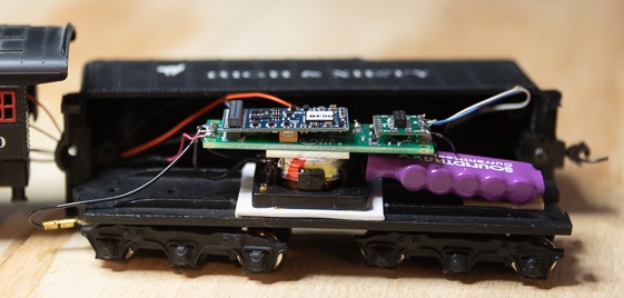
Note that the connector on the decoder and daughter board are both UP. The current keeper had to be installed at an angle to clear the coupler pocket. It was attached with some double faced tape. I used 3mm LEDs from Jameco www.Jameco.com for the head light and rear light. Jameco has good hobbyist pricing. Just be sure you buy enough stuff, like wire for your feeders, to get the most out of their shipping charges. I wanted warm-white LEDs, but they didn't have any in the 3mm size at the time I placed my order. I used part number 2174881 which is more of a daylight white. For the rear light, you will need to drill out the non-existent headlight in the rear. I suggest you use a tiny drill bit to start with and work up in a couple of sizes to the size of your LED so that your drill stays centered. Drill holes, as necessary in the floor of your tender for your speaker. I used a speaker I had in my parts bin. I like speakers that are as large as possible and have good movement of the cone (throw) for good bass. I cut a 1" diameter hole in a piece of styrene (which was suitable for my particular speaker) so that the speaker cone could move forward without hitting the bottom of the tender. I used a piece of 0.06" thick styrene. 0.04" thick styrene would probably work as well. I have not tested what the minimum necessary thickness is, but I'd hate to glue the speaker to the styrene and then to the tender and later find out I didn't allow enough. If you use a sugar cube speaker make sure you adjust the volume down before hooking up. Sugar cube speakers can't handle the full power of decoders. After gluing your speaker into place, solder wires to it. Attach your Decoder Buddy to the back of the speaker with double-faced tape. Now is the time to think about how you want to run the wires from the tender to the locomotive. I thought about running the wires down and out of the bottom of the tender. But the way the shell and chassis work together, I was worried the wires and wheels would interfere with each other. If you want to take advantage of the daughter board's ability to offer you connection to the rear light and still be able to completely remove the tender shell, you would have to hack a big inverted "U" in the end of the tender. I figured that once I was done with the decoder installation, I would probably not need to remove the tender shell. So I decided to go out the end of the tender and drilled a hole to pass all the wires through. I would lose the advantage of being able to remove the shell and set it aside, but it would look better and not ruin the sealed enclosure nature of the tender shell as much as a big U channel would be. It is desirable for good bass to seal off the area behind a speaker from the front. Like I said earlier, I was impressed with how good the speaker sounded even before I put the tender shell on. So it is your option if you want to seal the hole for the wires with RTV-type caulk. Attach the track pick-up wires to the (T) terminals on the mother board. You can use existing screw connections to the tender chassis and locomotive chassis. If you are industrious, you can attach wires to these chassies that are hidden from view. There are T's at each end. For this installation, I used the T's nearest the locomotive. (For a diesel, you might use both sets of T's - one set to each truck.) Attach the speaker wires to (S). Use the terminals at either end. Attach two wires for the motor to the mother board, but do not attach them to the motor yet. Instead, clip the wires to the motor. Be sure they don't touch the motor can, frame, or locomotive chassis unless you don't mind damaging your decoder and buying a new one. Power up your track and select address 3 and select the forward direction. The speaker should start making sound. See if your locomotive goes forward. If not, swap the wires to the motor and try again. Once you have the locomotive going forward, power it down and permanently attach the leads to the motor. You're half done! Clip the leads to your LEDs to about 3/8" of an inch. Solder wires to the LEDs and cover each lead with heat shrink tubing. Temporarily put a 1k-ohm to 2.2k-ohm resistor in series with one of the leads and touch the other end of the resistor to the terminal on a 9V battery. Touch the other LED lead to the other 9V battery terminal. If it doesn't light, swap the leads to the battery. When you have it working, note which lead went to the battery's positive terminal. Set the resistor aside. You don't need it. The lead that went to the positive termina goes to the daughter board's set of four holes which are the blue wire common. Attach the other wire to the 0r terminal for the rear light and the 0f terminal for the head light. Power up your locomotive and make sure everything is working. If you want to use a current keeper (keep alive circuit), cut the connector off a Soundtraxx current keeper. Solder the blue wire to the U+ terminal on the mother board. Solder the black wire to the GND terminal. Be sure to hook up your keep alive circuit last. If you hook it sooner than as a last step, it will store power and you will have to wait for it to discharge each time you power up the locomotive during your installation. Close everything up! Enjoy your new locomotive! |
Copyright by Allan Gartner 1996 - 2020 © All rights reserved. You may print this for your own, personal, non-commercial use. Non-commercial, non-personal reproduction may be requested by visiting www.WiringForDCC.com/writeme.htm . All users, commercial and non-commercial, may link only to this site at www.WiringForDCC.com. Thanks r to all who contribute to this site and the Q&A forum! |