|
||||
Decoder Installation into an Powerhouse HO
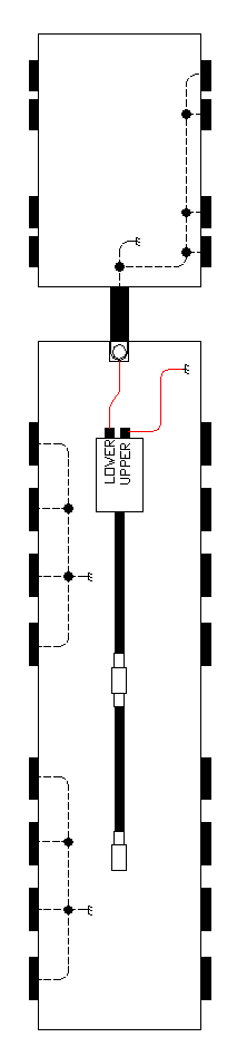
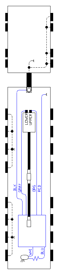
Not exactly to Scale! (Heck, it isn't even close!) Locked rotor stall current: 1A. For your information, I used a DH83FX decoder for this installation. Those two wires shown above are all the wiring there is! Simple, isn't it? Unfortunately, there is no head light. Bummer! I draw my drawings to bear some resemblence of the locomotive. Take special note of the red wire above that is attached to the upper terminal. It is going to the locomotive's left, but it is connected to the right wheels. Don't let this confuse you! The motor terminals are shown side-by-side above, but they are actually directly above one another. The chassis ground symbol is shown on both the tender and the locomotive. This is a common arrangementment where the wheels on one side are attached to the locomotive's chassis and the tender wheels are attached to it's chassis. The use of the chassis ground symbol does not imply that they are attached to each other. The drawbar attached to the locomotive is isolated from the locomotive's chassis. This locomotive comes apart fairly easily. The front articulated section is attached to the boiler via a bolt in a slot. At the back of the slot, the hole is bigger, and the front articulated section will come off. A splined universal joint decouples the drive power. Two screws secure the rear drive wheels. The back of the rear drive assembly is in a slot at the back of the locomotive. All you have to do is remove the two screws and slot the assembly forward a bit. However, the two steam pipes attached to the rear assembly may inhibit easy movement. The two steam pipes are snug fitted into the rear drive assembly. A little care and the whole thing comes apart. Pull on the air pumps on the front. The front of the smoke box will come right off. This will help installation of a decoder. Fortunately, the motor is already electrically isolated from the frame - once the wires are removed from it, of course. Disconnect the two wires from the motor, but leave the other ends attached to their points on the chassis and drawbar.
Install the decoder wired as shown. Connect to wires connecting to chassis and drawbar. Don't be a hero and try to solder to those terminal locations directy. Too much heat may be required and something nearby may be damaged. Instead solder the black and red wires to the wires that attach to these points. Don't forget to slide a piece of heat shrink over the wires first. It is a little tricky to keep the wires from contacting rotating parts. So your first inclination is to cut the wires to just the right length. This allows you to get the decoder partway into the boiler. The next time I do one of these locomotives, I am going to leave the wires full length. That will allow the decoder to be pulled all the way into the front section of the boiler through the hole in the middle of the boiler. (Yes, the same hole you didn't know was in the middle of the boiler until now.) So leave your orange and gray wires full length. Note: If you are reading this without having the locomotive apart, this "hole" I am referring to won't make much sense. It kind of divides the front of the boiler from the rest of the locomotive. You will see it when you take the locomotive apart and look down the boiler. Don't forget you will need the tender attached to try this locomotive out. No need to get that sinking feeling for a simple forgetful mistake like this! This locomotive does not come with front head light. I drilled the head cast head light assembly with a very small drill bit followed by a 1/16" drill bit. A 1/16" hole allows an easy fit for the grain of rice light bulb I used. You could use a smaller hole if you wanted to. My bulbs are supposed to be 1.2mm in diameter (0.047"). Drill gently on the locomotive. The heat of drilling will probably make the soldered head light casting fall off the locomotive as mine did. Consider that a blessing! Now it is easier to drill - ideally with a small drill press if you have one. I hand drilled mine without a problem. Glue the casting back on when done with the locomotive. I glued the grain of rice bulb in with a tiny dot of CA cement. This should make it possible to remove the bulb when it burns out. Don't glue the bulb in until you are all done with the locomotive. Note a grain of rice is much smaller than a grain of wheat bulb. A grain of wheat bulb is much to big to be mounted in this cast head light assembly. A grain of rice bulb typically operates on 1.5V. Be sure you have read my section using grain of rice bulbs. Strip the grain of rice bulb wires extremely gently. It barely takes any squeezing effort to strip the insulation on these bulbs. I left about 2" of wire on these bulbs. Leave 4"! For one thing, if you frequently cut through a wire while trying to strip it, you will definitely want to start with 4" if not full length. Leaving more than 2" will make it a little easier to position the resistor inside the boiler. My tender appears sealed. I chickened out trying to open it and drilling the rear for a head light. Slide the decoder and all the wiring through the hole in the boiler toward the front. Tape the four wires that run past the motor to either side of the motor. Reassembling the locomotive is not quite as easy as it was getting apart. Lining up the spline for the front drive assembly can be trying. But when you finally have the two splines lined up correctly, it will slide together easily. So if it isn't sliding together easily, they aren't lined up. Yes, I know they look lined up! But if they aren't going together easily, they aren't. Don't forget to hook in the front steam pipe before trying to hook the splines together. How do you get the head light in place??? First thought is stick it through the slot for the steam pipe. I gave this serious consideration but then chickened out. It wouldn't take any effort on the part of the steam pipe to cut through the insulation of the grain of rice bulb. I then thought about running it right out the front of the smoke box and gently pressing the smoke box cover back in place. This does work, but be very careful. I think if you remove this cover a few times, you will eventually, if not quickly, cut through the insulation. The smokebox cover also tends to fall off if you do this. I then used my dremel to file a grove in the back bottom side of the smoke box cover. The goes well with the notch in the front bottom of the smoke box. Using a hard grinding bit, it was easy to carve a smooth grove in the cover and allow for plenty of room for the wire to slide about. Take all the decoder wires you have left over and cut the ends off of them so that there is no exposed wire. Put all of them inside a piece of heat shrink and shrink it. Do not solder them together! While cutting them flush almost guarantees that they will never short to anything, especially the frame (which is tied to one of the wire pick ups), almost doesn't count. You need a guarantee. If no heat shrink, then electrical tape - though electrical tape leaves a messy residue. If you are still thinking about not covering these ends, think of these two things: How much is that piece of heat shrink tubing worth? How much is a decoder worth?
|
Copyright by Allan Gartner 1996 - 2006 © All rights reserved. You may print this for your own, personal, non-commercial use. Non-commercial, non-personal reproduction may be requested by visiting www.WiringForDCC.com/writeme.htm . All users, commercial and non-commercial, may link only to this site at www.WiringForDCC.com. Thanks to all who contribute to this site and the Q&A forum! |