|
||||
Powering Points Since some switch machines cannot throw points that are "stiff," we are now recommending that you drop feeders from your points to your busses instead of soldering bonds across the points. SOLDERING BONDS UNDER THE TURNOUT: Here is another method of providing a bod wire from the points to the closure rails that isn't too stiff. It involves using #24AWG stranding wire under the turnout.
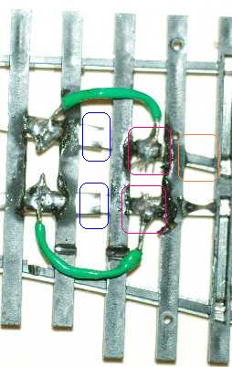
Above is a pair of bonds soldered across the joiner underneath the turnout. The wire is green so that it would show up easier in the photo. I used #24 AWG stranded wire so that the least amount of springiness would be added to the points. Notice that joiner end (blue highlight) is in the center of the photo. It acts as a hinge. To prevent your points from becoming too stiff, do not solder here. To prepare the turnout for the wire attachments on the right, trim the thin plastic strips (red highlights) from between the ties with a sharp knife. You can see examples of such strips in the photo above between other ties (orange highlight). Do the cutting with the turnout on a table top. Do not hold it and cut as the knife may slip and cut your fingers. While this task is probably best accomplished with a resistance soldering station, I did the above with a 35 Watt pencil soldering iron just to see if it could be done. To solder on the wire using only two hands:
SOLDERING BONDS ON THE TOP SIDE OF THE TURNOUT:
This is the old method that is too stiff for some turnout machines. If you have switchmachines, like the Switchmaster (Hankscraft) that can throw such turnouts, the choice is yours. Here is how to solder bonds across the points should you choose to do so.
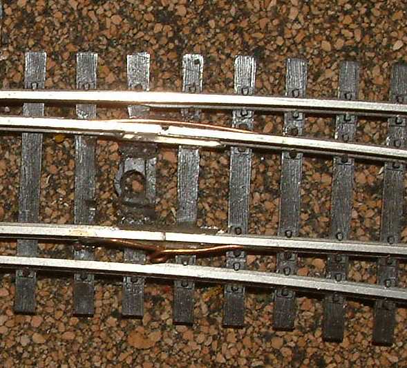
This shows several things. a) Using joiners to replace the hinge. b) a straight bond. c) a more flexible bond with a loop in it. Note: Some people find their switch machines cannot operate points with additional stiffness (Hankscraft motor driven ones do not have this problem. See section on Parts on obtaining these.) Alternately, it is perfectly fine to drop feeders down from the points to avoid the added stiffness. Refer to the switch diagram above. I suggest you use solid wire of size between 18 AWG to 24 AWG to make the jumpers (called bonds) between the closure rails and the point rails. Except for option 1 below, remove the jacket completely before you start. It is simply much easier to work without the jacket and easier than stranded. Plus the solid will not wick the solder and get too rigid. Feel free to use any size listed that works well for you. Do not feel compelled to go for 18 or 20 if you are having trouble with it. 22 will work just fine. Option 1- This will add some springiness. This is the option I personally like. The springiness is definitely more than you would have with the rivet, but compared to a BK Enterprises switch, which has no pivot at all, the springy-ness is no worse. I use Hankscraft (Switchmaster) stall type slow-motion motors, so the springiness is not a problem for me. Simply take about 1" of bare solid #24 or #22, and lay it straight against the outside of the point rail after it has been slid into the joiner. I used a medical clamp to hold the wire in place. I found with my pencil soldering iron, I could get a good solder joint quickly. Make sure the wire is shiny and that you are using a new switch (without oxidized rails), or use a sanding sponge to shine the rail so it will readily take solder. Since my switches are new, I did not have to do anything special. Do not be afraid to use an 1" to 1.25" of wire to do this. The longer the better - being less springiness. Weather it after you are done. As you watch the switch before you take it apart, you see the point rails move closer or farther away as you operate the turnout. Obviously, this technique inhibits that. I wondered if that would inhibit the throw bar. It seems to work just fine. Option 2- If soldering definitely is not your thing and/or you want the guaranteed way to get power to the points with a minimum amount of springiness: Attach a wire to the outside of each point near the pivot BEFORE you slide the rail into the joiner. Drill a hole through your layout under each wire. Attach these wires to the feeders for your switch. Note: If you choose this option try not to use a size smaller than 20 since the length will be much more than an inch. Also note: the bigger the number the smaller the wire! So use 18 or 20 for this option. Option 3- Requires you to have the soldering finesse that you would need to attach any set of wires to your track. This option probably won't have too much added springiness. Solder a wire to to the point rails as in option 1. This time use 24 or 22 stranded. If you do not mind the springiness, 24 solid would also be good. 22 solid would be my first choice. 22 solid would also be the most springy. Now instead of drilling a hole through the layout and ending up with extra feeders, run the wire and attach it to the outside of the nearest stock rail. At worst, you might have to notch your cork or homasote for this small wire. To reduce springiness, do not attach it at the nearest spot (about 3/16" away) on the stock rail. Maybe attach it an inch or so away on the stock rail. This should make it springiness-free like option 1. Option 4- It allows some movement of the points that option 3 might not. I don't think doing it this way is necessary. But it's your railroad! Take about 1.5" of bare wire and wrap the middle of it 1 full loop around a 1/16" drill bit or something about that size. Then trim it to be about an 1" or so long. Solder on as you would on option 1. While positioning the wire, that little loop seems to want to point up. Instead of fighting it to point down, as I was for 5 minutes, just solder one end down. Now you are in control! Bend the wire so the loop hangs down. It will now stay put. Solder the other end to the outside of closure rail. Option 5- Is a little "u" shaped jumper (called a bond). I think this might add springiness or make the bond stiffer than if you just used option 1. Again, it's your railroad! Be sure to have the loop hang down rather than to the side. Hanging down will reduce the springiness.
9. Solder the bonds on the outside of the rail. Do not solder the joiner. Too much heat. On track sections, I personally solder the joiners with a 140W gun or the resistance soldering station. Things are too cramped on a switch in the vicinity of the points and closure rails. We have to be dainty here. A nickel-silver rail with nickel-silver joiner plus a bond wire of some sort (options 1 - 5) should be trouble free. Installing Hidden Bonds: The following suggestion for hiding the bonds comes from Denny Anspach, danspach@macnexus.org Prototypical appearance of my turnouts is a high priority,
and in this regard visible wire bonds are a personal issue. In this
regard, one suggestion that I would make for your current discussion
on the subject is to apply the bonds between the closure and point
rails
hidden under the bottom of the rails, rather than on the top. In this
regard, I use #29 tinned wire soldered to bottoms of rails about 1 To do this, on the bench, I use a Dremel bit to carefully excavate a trough for the wire through the intervening ties and plastic webs, and completely cut out the web to uncover space for soldering the wire. I clean the rail bottom to remove mold agent (flux will not do it), after clipping heat sinks to the rail on each side (the heat sinks are stainless steel clips ripped from unused convention name tag badges), I solder the wire in quickly with a 40 watt iron. The #29 wire is fine enough that it does not cause untoward resistance to point movement, and the wire furthermore functions as an effective tether to hold the points into the connector. While I am at it, I also solder a short length of the same wire laterally to bond the closure with the stock rails. To the casual observer, no one sees these bonds, and the turnout is DCC friendly and visibly intact before it is even installed on the layout. Notes from Allan: 1) #29 AWG is rather fine wire. You may have trouble working with it. You should be able to achieve Denny's objectives using #26 AWG wire. #24 AWG may work, too, but verify it has not added too much stiffness to the movement of the points your particular switch machine. 2) I do not advise the use of light bulbs for isolating shorts should you use #29 AWG wire. If you use #29 AWG wire, you should let your booster shut the track down or use electronic circuit breakers. Sustained high current draw, such as in a short, will turn your #29 wire into a fuse! Please note that if you perform a sustained short test on a turnout you just modified, the #29 AWG wire will not break. This is because the majority of the short circuit current will be flowing through your rail joiner and not the #29 AWG wire. The #29 AWG wire will not become a fuse until your turnouts have been installed for a few years. Then your turnouts may start failing. You will loose the advantage of hidden bonds and will likely really hate yourself! So either use electronic circuit breakers with #29 AWG or use heavier wire like #26 or #24. 3) Denny's modifications were on code 70 track. Carefully test your soldering skills on a piece of track before working on the underside of your turnouts. You may find a different wattage soldering iron may be require. Also, you should find that a resistance soldering station works quite well for soldering on your bonds. Lastly, I suggest you use liquid flux and solid solder for making your connection as quickly as possible. See the section on soldering. |
Copyright by Allan Gartner 1996 - 2006 © All rights reserved. You may print this for your own, personal, non-commercial use. Non-commercial, non-personal reproduction may be requested by visiting wwww.WiringForDCC.com/writeme.htm. All users,commercial and non-commercial, may link only to this site at www.WiringForDCC.com. Thanks to all who contribute to this site and the Q&A forum! |