|
||||
Decoder and Soundtraxx Sierra Sound Installation into any Locomotive * * Okay, well maybe not a N or a Z scale locomotive. HO is a doable challenge. This is primarily intended for garden railroaders.
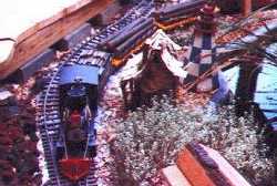
My Denver, South Park, and Pacific makes it's rounds on my Finchfield & Wrensylvania. This installation note assumes you have read the section on Wiring Specific Locomotives.
Why You Need These Generic Instructions These generic instructions have several key things you cannot get easily anywhere else and is why I created them for myself. In order to use the Sierra sound system with DCC, there are a few things you need. You won't need the battery to power the Sierra. Instead, you will need a very simple 12V power supply circuit. To use throttle sensitive chuff and other throttle triggered features like the whistle blowing, you will need to connect the Sierra throttle sensing wires to the motor output leads of the DCC decoder. To do this, you need a simple filter circuit. I got the filter circuit from Soundtraxx over the phone. It wasn't on their web site. The Soundtraxx web site does show how to hook the Sierra to a DCC decoder, however, upon careful examination of their web site and the Sierra manual, you will see that there is an error in one or the other concerning the trigger inputs for the sounds. Which is right? I figured it out and put it right here. I tied the DCC decoder, the Sierra, the filter, and the power supply all together in one convienent place for you and me. These installation notes can be used for any command control system, not just DCC. However, my color codings of the wires will, at a minimum, be different.
To the best of my knowledge, LGB motor/truck assemblies always have four metal posts coming from them as you will see in my schematics below. The power pick ups are the inner two and the motor are the outer two. They usually use the colors white, yellow, brown, and green. Sometimes LGB ties one of the motor and power pick-up leads together with a wire. Remove this wire and toss it. If you have an LGB locomotive that has only three or two leads coming from the motor and truck assembly, you will probably find that the power pick up and motor are tied together. You will have to take the motor/truck assembly apart and isolate them. Failure to do so will "let the smoke out" of your decoder and require a trip back for your decoder to it's manufacturer or a shorter trip to your trash can. I know that LGB has been making G-scale locomotives long before I could afford to have one. I don't know what you will find in these earlier models and can't promise how well these instructions will apply. Many, especially of the newer, LGB locomotives have a 5V regulator circuit and use 5V light bulbs. You can continue to use these lights if you add resistors. Resistors R1, R2, and R3, all need to be 1/2 watt resistors. I use 390 ohm resistors on my track that has 18V on it. If you are running 20V or higher on the track, you should use 470 ohm resistors. If you are running 18V, you could drop down to 330 ohms if you want a brighter light. You can also replace the LGB 5V light bulbs that are in the locomotive with LGB's 19V light bulbs that they sell. See the section on Getting Electronic Parts.
Openning Locomotives It can be a real project to figure out how to open a G-scale locomotive. It can be just as bad trying to close it back up! I highly recommend you video tape the disassembly!
Decoder Selection This generic installation instructions can be used with any decoder made by any manufacturer of your choosing. See Decoder Selection in the DCC in the Garden section.
Wiring The colors of the wires that come out of the decoder on my schematic are the NMRA standard colors. The pin numbers are for the Zimo decoder. Note, I do not show the wires going to the ribbon cable connector on the drawing. I did this simply because things would be too cramped making the drawing too difficult to read. I have drawn a Zimo decoder which does not have NMRA colored wires. So for the motor and power pick up, I have shown the screw terminal block that the Zimo MX65S has. The wires shown with the numbers are the numbers of the wires on the ribbon cable connector that the Zimo has. With the cab light wired to ribbon cable wire #13, function F3 on your throttle will operate your cab light.
Note: 5 and 10 are tied together on a Zimo decoder. If you have a locomotive with flickering firebox effects that you like, you certainly don't need to use those with the Sierra unless you want to. So you do not need to hook up those shown above. The Sierra does use these lights so that you can program it. So if you did not, or could not as frequently the case, mount your Sierra in such a way to see the LED's built onto it, you will need to add lights and the remote programming switches shown as well. Hide them under a wood pile, under a coal load, or inside a tool box on the tender or locomotive as appropriate. Owners of non-DCC command control systems: You can definitely use this circuit for your command control system. However, at a minimum, the color codings will be different.
Components C3: Electrolytic capacitor, 100uF or more rated at 50V or more. C4, C5: 0.01uF, 50V ceramic capacitors. 7812: 7812 12, 1A voltage regulator. If possible, mount to metal inside your locomotive. However, it must be electrically isolated any other electrical device also using it for cooling. Otherwise, you will let the smoke out of something and ruin it, as well as your day. Z1: Any bridge rectifier good for at least 1A and 50V. Magnetic reed switches for triggering whistle and bell using LGB track magnets. I'm going to try to get LGB to sell their trigger module. It mounts to a tender truck. It plastic encases the reed switches - which are extremely delicate. Gluing reed switches to the bottom of a locomotive or tender guarantees that a stone or something will damage them just before your guests arrive at your open house. I've tried a number of things and so far everything has been a miserable and quick failure. Any pushbutton switch can be used for a remote programming of the Sierra (connected to pins 1,2,3). Heck, I have even foregone the switch to get something that fits in the front of the smokebox. I have found the external switches that come with a Sierra don't always work. So in my firebox, I glued a three-terminal header pin - which is basically just a metal pin that solders into a circuit board and often used for connecting ribbon cables in computers. My "switch" is touching the middle terminal to either of the outside terminals with a screwdriver or pliers. Flickering firebox lights can be any 19V light bulb like that sold by LGB. R4, R5 should be 22 ohm, 1/4W resistors. L1, L2, should be 1000mH coils like that sold at Radio Shack. C1, C2: You will notice two back to back electrolytic capacitors, C1 and C2. Electrolytic capacitors are "polarized" and will explode if hooked up backwards. Got your attention, didn't I? Yes they do! They can be dangerous. You can buy nonpolarized ones, but Radio Shack only carries a limited number of them. Therefore, if you want to build this filter from parts you can get at Radio Shack, hook two electrolytic capacitors back to back. This is in fact how nonpolarized ones are made. I show that you should use two 2200uF capacitors back to back. If you buy a nonpolarized one, use a 1000uF. R1, R2, R3: See the Generic LGB Instructions above. See the section on Getting Electronic Parts.
For the Electronics Buff: If you don't care, don't read what follows. It may give you a headache! Why do I recommend a single 1000uF capacitor or two 2200uF ones? Few people now what I am about to tell you because you rarely need to hook capacitors in series. Capacitors in series are like resistors in parallel. Therefore, two capacitors of equal value will give you a total capacitance of half of one of them. Therefore two 2200uF in series have a resulting value of 1100uF. Don't worry that the back to back capacitors have a resulting value of 1100uF and I recommend a single nonpolarized of 1000uF. This circuit is very non-critical. 2200uF and 1000uF are simply commonly available values. BTW: Don't believe me about what happens to capacitors in series? Ever build a DC power supply and hook capacitors together to get more capacitance? You hook them in parallel to do this. You've probably done this, haven't you? See, they are completely backwards the way you would think about resistors. One last BTW. Resistors and inductors are alike. Only capacitors are different.
Free counters provided by Andale. |
Copyright by Allan Gartner 1996 - 2006 © All rights reserved. You may print this for your own, personal, non-commercial use. Non-commercial, non-personal reproduction may be requested by visiting www.WiringForDCC.com/writeme.htm . All users, commercial and non-commercial, may link only to this site at www.WiringForDCC.com. Thanks to all who contribute to this site and the Q&A forum! |