| |
||||
Signaling Considerations for Signaling I'm retired now. I FINALLY finished a layout enough that I could implement some signaling. The electrical things I thought about before building my new layout. Mechanical things I didn't. Here I will discuss the electrical things I thought about and all those mechanical things that caught me slightly unprepared. 1. Set up blocks when you build your layout. This includes two things. One, gap all your rails where you need them when you build the layout. This will be very difficult to do later. Two, put your sub-buses in NOW. Otherwise you will likely need to almost completely rewire your entire layout later. It is optional if you spend the money now for block detectors. I chose to put the block detectors in when I built the layout. It's a little easier if you do this now, but not a disaster if you don't. I used NCE BD20 block detectors, but now that I got into LCC, I see that RR-Cirkits also sells block detector electronics. Note: If you don't have an NCE system, no problem. The NCE block detectors work just fine with other DCC systems and RR-Cirkits LCC electronics.. I just wanted a "low" cost signaling system. Maybe I should say "lower" cost. It's not fancy and not modeled after any particular prototype system. My layout is "small" (760 sq. ft). I only intend a few operators and no designated dispatcher. If you want to follow a particular prototype, you need to think about that NOW and make sure your track gaps and sub-buses are appropriately installed. Here's an example: I only gapped the tracks leaving my turnouts. So my turnouts are part of the block leading to the turnout. So my signals don't change until the locomotive enters the next block as it leaves the turnout. You might want the signal to change as soon the locomotive enters the turnout. If you want this, you probably will need to put gaps on the heel of the turnout, too, and may need a block detector just for the turnout. If you want your signaling system to know which way your turnouts are thrown, I suggest hooking up wires to your switch machine now. This will save you having to work over your head later. 2. Block detector sensitivity I use Frog Juicers and NCE block detectors. The NCE block detectors have the ability to change their sensitivity. (RR-Cirkits block detectors do, too, but I have no experience with them and can't comment on them.) I also have block detection within a reversing section and used the circuit below to indicate reversing section polarity. I didn't have any trouble with the Frog Juicers, but the current drawn by the LEDs in this circuit caused a false occupancy indication. Don't panic. Just reduce the sensitivity a bit. At the moment, I am using a 1200 ohms resistor with the NCE detectors to reduce their sensitvity. I'm going to try several more locomotives and rolling stock with resistors on their wheels to trigger block detection before I am sure that 1200 ohms is indeed the right value. Note: The 1200 ohm resistor goes on the BD20. See the BD20 manual for details. The resistors used to indicate reversing section polarity are still those indicated in Don Vollrath's circuit below. 3. Locating signals along your layout. Signals don't take up a lot of space, so I didn't give a lot of thought when I built the layout as to where I was going to put them. Because I wasn't worried about being prototypical, it all worked out in the end, but I would have been better off if I had given this some forethought. Examples of problems I encountered: - I had a spur leaving my mainline right ahead of a siding. The signal I intended for my siding would have ideally been located where the spur track was. I ended up putting the signal on the fireman's side of track leading to the siding. Horrors! - When you need to place a signal between a siding and a mainline track, leave enough space for the signal. If using a dwarf, may be less of a problem. Note: One of my clubs had to move some dwarfs because of long rolling stock overhang. - If you want a signal near a turnout (who doesn't?), be careful not to drill through your switch machine. (No, I didn't make this mistake.) You might need to relocate your signal a little bit. Conversely, think about which way to face your switch machine under your turnout to minimize the possibility of this being a problem. I'm thinking of the very popular Tortoise switch machine as I write this. - If you have mountains and such along your layout, leave enough space for your signal before starting your mountainside climb. With my vegetation in place, this was almost a problem for me. - The last thing to consider when building your layout is where are your risers and other layout support carpentry located with respect to where the signal is going to be. We all think about this when building the layout for the switch machines, but I suspect most of us never thought about signals before. 4. Costs In general, you will need block detectors, signal electronics, signals, cabling to the signals and block detectors, and cabling between your signal electronics modules. I'm thinking about LCC signal nodes as I write this. Layouts using multiple Arduinos will have a similar need. I chose to use Tomar signals. They look great and are pre-assembled. I can't work with tiny, delicate things like signals, so they were worth their cost.to me. A much less expensive way to go is use Digitrax signals. They are pretty basic and you can jazz them up a bit if you want to make them look a little more realistic. Digitrax signals can be used with RR-Cirkits LCC signal modules or Arduinos. If you are using Arduinos, you will need current limiting resistors. The RR-Cirkits signal module does not. Think about how complicated (prototypical) you want your signaling system to be. I just put a 3-over-2 signal at the entry of each passing siding. To be honest, it is easier for an operator to just look at the track ahead than look at the signal to determine if the track ahead is occupied. Also, with the hood over each light, an operator would have to look pretty much straight ahead to see it. So when I start operations in a few months, how realistic is my expectation that operators will even notice the signal indication. Fortunately, I only want signals to add a bit of animation to my layout. As it is, I spent several thousand dollars for what I have. That cost could easily triple if I knocked myself out being prototypical. Introduction to Computer Controlled Signaling You don't have to use a computer, but it seems everyone wants to use JMRI. Probably the main reason is that people want to use it as a control panel. That's a good enough reason, but there are a few others. It is more flexible than most hardware implementations that do not use a computer and it is probably easier to debug your signaling system. So I will assume you, too, have decided to use a computer and most likely, JMRI as well. Since I first wrote this several years ago, several new products have hit the market. They are Arduinos and LCC. Like I said, it's been several years ago that I updated this page. The information below was initially written regarding using JMRI to control your signals. Not only have new products arrived, but I have moved and built a new layout. I'm also retired, so I have finally finished a layout and implemented signaling. Now I have something more to write about! I mulled over Arduinos or LCC. Either one will work and the cost isn't drastically different. The pro's and con's don't lean particularly one way or the other either. Both Arduinos and LCC don't require a computer for them to operate. You can if you want to. I don't want to have to boot up my computer and launch JMRI every time I want to run trains. I finally settled on LCC. I did this because: 1) It's a product that is intended for model railroading. 2) It has built-in networking capability that allows communication between modules, called nodes. I wouldn't have to invent this and connecting my computer to the end of the network, I could easily work on any of the nodes in my network. (I have 4 nodes) Whenever I hear from someone who is building their first DCC layout, they have a lot of enthusiasm and want to put in signaling. That's great, but there are some serious considerations before doing so. When you put a decoder in a locomotive, you hook up the track wires and hook up the motor. Try it out. Good! Then hook up the lights. Try it out. Still good! Set the locomotive's address and you are done! When you build your layout, you hook up the booster to the track. Put on a locomotive and try it out. Things are looking good! Now you can enjoy your trains. Life is grand! Signaling is another animal altogether.... Serious Consideration #1: Signaling will likely cost you more than your total investment in DCC to date. For many people, this is all they need to hear to have second thoughts about signaling and scrap the idea. It isn't that signaling hardware costs so much. The problem is it takes a lot of hardware to implement DCC signaling. Rather than just needing a booster or two and a handful of sound-equiped locomotives to get started, you will need a block detector circuit for every single block you will need to detect. You will need a module to send the output of the block detector to the computer. You will need to hook up this same module to send your turnout positions to the computer as well. You will need a computer interface for your signaling system. You will need modules that will drive your signals. And, of course, you will need the signals themselves. For more than a small layout, all this hardware will add up. Serious Consideration #2: You will need the help of someone with an electrical or computer engineering degree. Signaling wiring is simple in concept; at least to an engineer. So what's the problem? The problem is getting all the stuff to work together. Everything needs to work for a single light to go from red to green. There are a lot of things that can go wrong. So you need someone or a team of people who understand the whole system and who has some serious troubleshooting skills. In the end, it will be a wire that came loose or a bit in JMRI that isn't set right. But finding that problem is much more difficult than figuring out why your locomotive decoder isn't working right. If you are new to DCC and don't have significant electrical and software skills, you will probably need a lot of help implementing signaling. If you have trouble getting a decoder in a locomotive working, you had better start sucking up to someone that has the skills you don't. Something Else to Think About: The number of years since I started my railroad and the present was longer than I would have liked. When the railroad was started, I started installing block detectors. Since progress was slower than I would have liked, I stopped installing the block detectors. I figured, probably like you, that I can install them later when I get around to installing signals. Now that I'm going back and installing those block detectors, I'm wishing I had done a better job of documenting where they would go. Worse, remembering where I had put those perfectly concealed insulated joints between blocks is difficult and finding them is worse. So if you can't afford the cost of installing the block detectors now, make flawless maps of your layout and under your benchwork of where your blocks are and where the block detectors need to go. Good news! Current transformers used for many block detector systems are now about $1 each and all you have to do is slip a wire through them. So I suggest that you install these devices now when you start your railroad. You will still need the circuit to utilize the output of these devices, but you can definitely add them later. For now, get your current transformers installed. You will still need to carefully document where they are located, what block they go with, and exactly where that block starts and ends. Having the current transformers installed now will help you know later of where to hook up the rest of your signaling system. And Now for a Non-Electrical Tip: Before I planted my first signal mast, I worried about how I would do so to avoid damage when track is cleaned or when someone reaches to uncouple a car. I tried to think of breakaway connections. Nothing I thought of excited me. Then my friend, Ken Klaviter, introduced me to an adhesive called Aleene's Tack-It Over & Over. You buy it at craft and hobby shops. This is a re-usable adhesive. He uses it to install decoders. You can use it to stick two surfaces together, pull them apart, and then restick them together. This may be just what I was looking for. I'm hoping someone can knock over a signal and simply put it back in place. I don't know how many times you can do this and how many years resticking will be possible, but for now, the prospects look good. We installed our first signal this way a few months go. Time will tell if this is the solution to the breakaway problem.
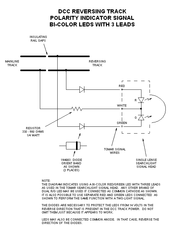
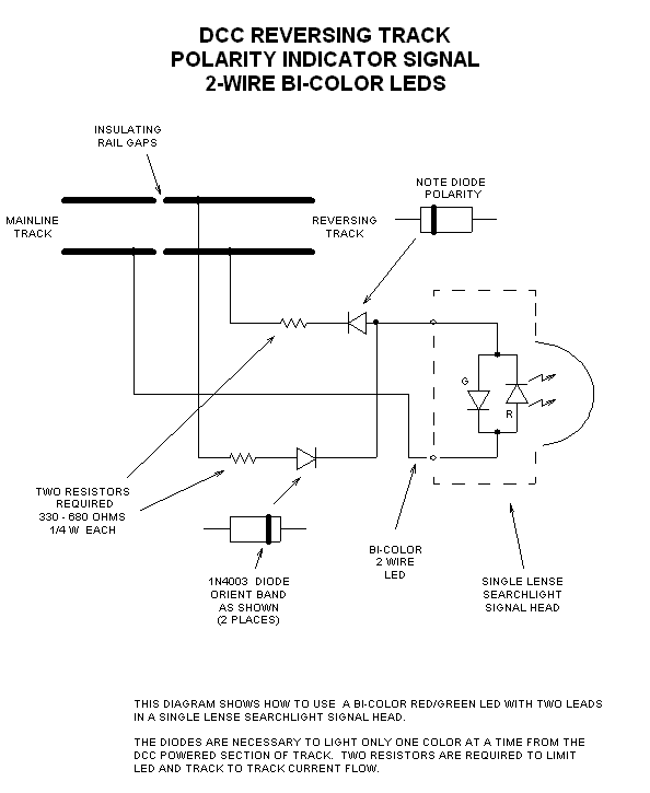
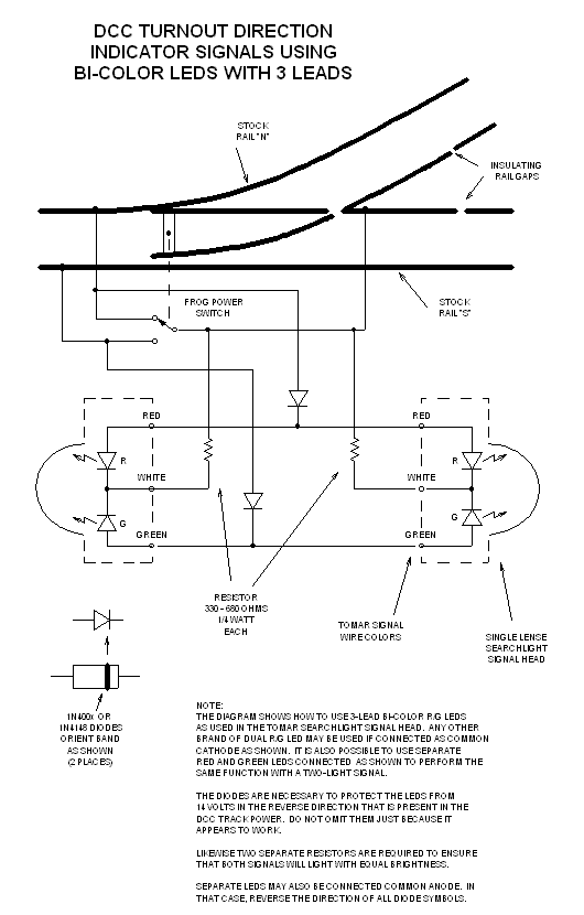
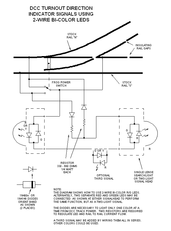
Circuits for the following signals have been contributed
by Don Vollrath. Indicating Polarity of Reversing Section Use this circuit to indicate if a reversed section of track is at the same or opposite polarity from the mainline track. This first circuit is for use of a 3-lead bi-color LED or two separate LEDs.
This second circuit uses a 2-lead bi-color LED.
Indicating Turnout Position Use this circuit to indicate the position of your turnout. This clever circuit works on DCC because DCC has a constant voltage on the track. This first circuit is for use of a 3-lead bi-color LED or two separate LEDs.
This second circuit uses a 2-lead bi-color LED.
|
|
|
Copyright by Allan Gartner 1996 - 2026 © All rights reserved. You may print this for your own, personal, non-commercial use. Non-commercial, non-personal reproduction may be requested by visiting www.WiringForDCC.com/writeme.htm . All users, commercial and non-commercial, may link only to this site at www.WiringForDCC.com. Thanks to all who contribute to this site and the Q&A forum! |