DCC for Beginners
|
||||
DCC for Beginners
|
||||
Computer-aided Model Railroading Please be sure to see Do It Yourself for others interested in developing computer control systems. See the Manufacturers page for software that you can buy or get free to operate your model railroad. What Should You Display On Your Computer? When you first consider signalling and block detection, you probably envision displaying the signals on your computer display. Yes, red, yellow, and green in both directions. But after acting as dispatcher for a friend's layout, I think this is unnecessary. As dispatcher, all I really care about is block occupancy and mainline turnout position. JMRI color codes the locomotive icons so I know what direction they intend to go. A final note on turnout position: Turnouts do not have to be DCC controlled to display their position on your dispatcher panel. (Dispatchers often control mainline turnouts, but this is not required for position indication.) Note that I'm suggesting that block detection without signals is very useful and may be all you need; meaning install block detection and signals later as time and money allow. Why not display display all the aspects? After all, that would look really cool, wouldn't it? The display would be uncluttered, you could make the layout map smaller, and most importantly, you could use fewer monitors. I had envisioned using three monitors for my layout, but with this new thought, two should do it; maybe even one! If you do opt for displaying signals, consider using the searchlight type on your computer display to minimize the clutter on your display. How many blocks should you use between towns? See my section on block detection. After having acted as dispatcher on several railroads, road crews are not as disciplined as a real road crew would be. After all, this is supposed to be fun and no one is operating under the threat of losing their job. So no matter how hard you try to get road crews to tell the dispatcher what they are doing, they will do something they shouldn't. For example, they will proceed to the next town without checking with the dispatcher. This leads to "cornfield meets" (collisions). So even if you don't have block detection, consider putting in at least red and green signals on your layout and then try to get your operators not to blow past red signals. So while you don't need every aspect displayed on your control panel, a simple control and indication would be appropriate for this type of layout. INFORMATION #15-1: For Information DCC Control of Turnouts, Go To the Section On Turnout Control. INFORMATION#15-2: Manufacturers and Non-Programmers: An Argument For Ladder Logic. Non-Programmers: Read this. If you
like it, let your favorite manufacturer know!
Manufacturers: Consider this alternate method for programming your computer control systems. I've programmed in just about every high level and assembly language there is. Like many programmers, I thought ladder logic was a joke. It's no joke. For some applications like controlling machines (read model trains), it's ideal! It's worth a serious look. Most PLCs program using a graphical interface that shows relay contacts. This method of programming is even easier to learn than procedural language programming like C or BASIC. Many people who wouldn't dream of trying to learn to program a computer, do ladder logic and do it well. This is because that for the most part, ladder logic could really be implemented using relays. This is a visualization process that is easier to grasp than bytes, memory pointers and for-next loops. This makes it very popular.
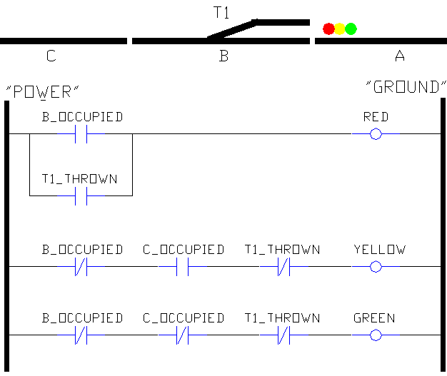
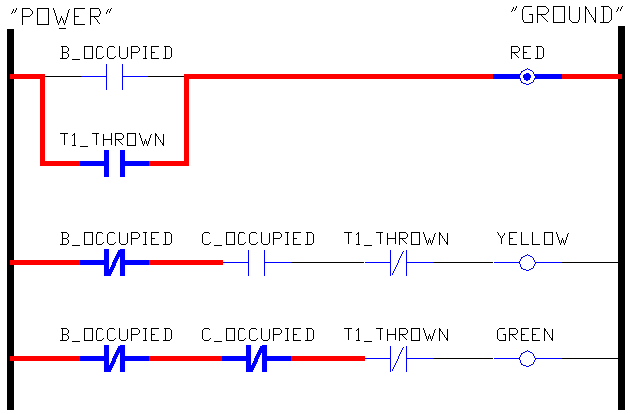
Here is the above as it might be written in a computer language. With the exercise you just did, you should be able to make sense of this below. If B_Occupied or T1_Thrown Then Red Which approach agreed with you more? If you thought you understood it, but now you don't, don't feel bad. Now you appreciate ladder logic! Below is an example of what you might see if the T1 turnout is thrown. In this simple example, T1 being thrown is all it takes to cause the red signal to light. It shows that blocks "B" and "C" are not occupied. Any input that is active is highlighted. Then the power is highlighted from left to right as far as it can go. Only the first rung makes it all the way across.
Troubleshooting is a breeze, too. I have been called to assist repair of machines that were totally unfamiliar to me. All I had to do was ask, what is the next thing this machine should be doing if it was working right? I'd search for the output that controlled that function. Inputs on the screen that were active would be highlighted. Just look at the rung from left to right, looking for inputs that weren't active, but should be. Then the sensor for that input was bad, needed adjusting, or a wire had broken or come loose. Total time to identify problem: under 15 minutes. In a model railroad, look for the block that has a train on it, but its input wasn't highlighted. What makes ladder logic so successful as a troubleshooting tool is the graphical user interface. So manufacturers, please give this some serious thought. I realize is a simple example. I'll be glad to discuss with you how ladder logic deals with timing, latching, comparing, counting, and more complex issues like math, dealing with data files and communicating on a network. I made those PLCs justify their cost every day! A-B, I believe, now has their PLC-5 series being emulated on a PC. They are proud of their products and charge accordingly. I have a few good contacts at A-B and might be able to get to someone in A-B who might be in a position to licensing some bit of their technology at a reasonable price.
FAQ'S FAQ #15-3: Can I Use A PLC? A programmable logic controller is an industrial control computer. It should not be confused with a PC — the personal computer you are using right now. PLCs use something called ladder logic. When graphically displayed, it looks like rungs on a ladder. See above. Many have logic elements that light up as a particular input is made. Allen-Bradley's progressively lit rungs make troubleshooting easy. Until I actually worked with PLCs, I looked down at them as most programmers do. I was a hard sell. In the old days, they simply mimic'ed relay logic — which was the use of relays to control things. How smart could a cabinet full of relays be? Not very! The modern PLC is sophisticated. It is ideally suited for controlling many things at once — like several model trains! They typically have LEDs on their inputs and outputs. So looking at the front of the PLC, you can get a good idea what inputs the system is getting and what outputs it is controlling. In a factory, this is a big plus. Many technicians can troubleshoot a machine without hooking up a terminal to the PLC and looking at the program. If programming isn't your bag, this is very nice. Of A-B, GE, and Siemens — the three biggest PLC manufacturers — A-B was by far the best. Easiest to use, reliable, system software that was bug free, operated just like the manuals said, and never crashed. Don't you wish your PC and its system software could be like this??? The systems that have lots of inputs and outputs are quite expensive. They do offer scaled down versions that are ideal for running things like candy machines. These units have limited expandability and typically have more inputs than outputs - since the typical machine needs more inputs than outputs. Anyone thinking a PLC for model railroading is probably thinking signals. Here you need a lot of outputs compared to inputs. So these low cost models are not usually adequate for our needs. Another thing to watch out for is that many inputs on these industrial machines are looking for 16-24V for an input signal — since 24V is what is typically used to run machine controls. Some DCC block sensors only put out about 5V. Typical PLC inputs would not detect this. The way to look at PLCs is to see if you can do what you want to do for less than $14 per function. That's what a function, like a crossing signal, costs on a DS54. The DS54 can operate rail switches, crossing signals, and a few other things for the creative modeler. And you can network it, too! While I feel that ladder logic is ideal for programming your DCC computer control system, the lack of low cost PLCs with lots of outputs makes them an uneconomical choice. The one place a PLC may be the right thing is turntable control. You still have the problem of it not talking to your DCC network. Using DCC products on the market today, I haven't worked out how this might be done. In about a year, I will face that challenge. So stay tuned. FAQ #15-4: DO I Need A Computer for DCC? Absolutely, positively not! Unless you buy a super low cost DCC system that says "uses your computer to save you money," the answer is definitely no. The mainstream systems on the market today do not require a computer.
FAQ #15-5: Would A Computer Help Make DCC Easier to Use? Except for loading speed tables, the answer is no. For one thing, the current DCC systems are not that hard to use. For another thing, a computer is hardly a walk around throttle! Lastly, setting up a computer to display your layout, indicate block detectors, and turnout positions is a good bit of tedious work. If you are brand new to DCC, trying to start out with a computer is a good bit of additional complexity you don't need. As I noted above, most DCC systems will work just fine without them. Adding a computer later won't obsolete anything you buy now. So take two small steps — buy a DCC system, add a computer later — rather than a quantum leap to the computer. IF YOU WANT TO GET SERIOUS ABOUT USING SPEED TABLES, then yes, a computer will make it much easier. Setting up speed tables without a computer is tedious. Fortunately, using a computer to set up speed tables doesn't require you to be a computer programmer.
Computer Control Software Suppliers Please see the Manufacturers section for suppliers of DCC computer control software.
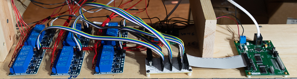
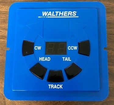
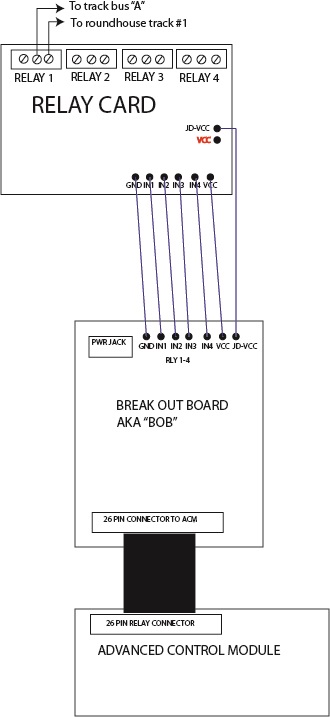
Roundhouse Track Power Control When Using a Walthers Turntable Advanced Control Module |
| eBay Supplier | Description | Part Number | Qty | Comment |
| 5V, 4 channel relay board for Arduino | eBay | 4 relay card, active low | Buy in groups of 4 as needed. | ||
26-Pin (2x13) Female to Female 2.54mm-Pitch 26-wire IDC Flat Ribbon Cable | eBay |
26 pin ribbon cable with connectors on each end | 1 | ||
| 2x40 header, 2.54mm pitch | eBay | 2x40 male header | 1 | ||
| 1x40 header, 2.54mm pitch | eBay | 1x40 male header | 1 or 2 | Break off groups of 7 as needed. You will only need 1 if you are using 5 or less relay cards. Order 2 if using 6 relay cards. Note: This particular eBay supplier sells them in packs of 10. More than enough for any project. | |
| DC Power supply socket. 5.5 x 2.1mm | eBay | 2.1mm power jack | 1 | ||
| 40 pin, female to female "Dupont cables" | eBay | 40 conductor FEMALE to FEMALE cables |
|
If you need longer, you can get male to female ones to make extensions. The colors repeat on the 40 conductor cables. I suggest you use the same seven colors as you go from your BOB board to the relay boards. One cable can do 4 relay boards. | |
| 5VDC, 2A, wall transformer with 5.5 x 2.1mm plug | eBay | 5VDC wall transformer | 1 | A wall transformer that puts out about 200mA or more is fine. You just need one with the 5.5x21mm plug at 5VDC. |
Preparation:
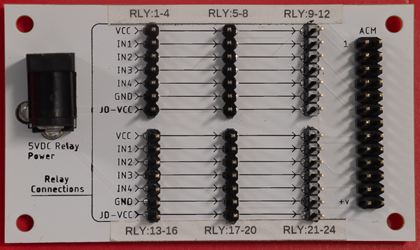
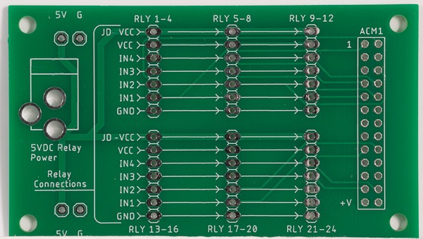
1. Assemble your BOB. It only goes together one way.
2. Install your ACM by hooking up the cable to your turntable's controller.
3. If you are controlling your turntable with DCC, hook up the ACM to your DCC track bus. You will need to assign DCC accessory addresses to your roundhouse tracks. See the July 2021 "DCC Currents" in Model Railroader.
4. Prepare the 26 pin ribbon cable and connector. Make it look like in my photo. This doesn't need to be any longer than you need. Assemble the cable and connector by laying the ribbon cable in the connector, then use a channel lock pliers to close the back of the connector onto the insulation-piercing tines. Don't adjust too tight and crush the connector! As long as the back is all the way on the connector and the ears on the back can mate with the connector body, you are good. You will likely need to crimp each back three times - left, middle, and right.
With an ohm meter, check that pin 1 of the connector at each end has continuity. Check pin 2. Check a few other pins at the opposite end as well.
5. Remove JD-VCC/VCC jumper on relay card. Place the jumper over the VCC pin leaving the JD-VCC pin exposed. You will be hooking up the JD-VCC pin in a moment.
Installation:
Install a little bit at a time and test as you go. Follow what I tell you carefully and your installation should be as successful as mine was.
1. Connect your 26 wire cable between the ACM and the BOB. I noticed that my 26 pin connectors had not crimped on the cable completely square. Electrically, it was good. So if you don't get yours perfectly square, it is not a big deal. The key thing is that when you screw down your BOB, make sure there is no strain in the cable. This could present a problem over time.
2. Mount your first relay card. Prepare a seven conductor cable of Dupont connectors. Carefully connect the seven wires to the BOB for the first relay card. Then connect the other ends to the relay card. Make sure the connections and colors on the BOB match with the relay card. Note that white and gray are next to each other and are nearly the same color. Make sure that you don't have any crossed connections.
You will notice that the BOB has 7 positions and the relay card has 6 side-by-side. The seventh wire on the relay card goes to the JD-VCC pin.
3. At this point, you can run some initial tests of the relay card. Move your turntable to the first four positions. A LED on the relay card should light corresponding to the first four tracks as you go through them. When all four LEDs light for the four tracks, you can pat yourself on your back. You did good.
4. Connect your wall transformer on the BOB. Now test your four tracks again. This time, you should hear relays clicking. Time for another pat on the back.
5. Now connect the "A" track bus wire to the center screw for the first relay and connect the right screw of each of the three screw groups to your "A" rail round house track number one. Connect the "B" track bus wire to your "B" rail fo the same round house track.
Command your turntable to track number one. A loco should be able to roll off the turntable and onto the first track. Make sure your loco goes completely off the turntable so that you are sure it is getting power from the first track.
6. Repeat step 5 for the three remaining relays on the first card.
7. Install your next relay card and repeat steps 2 through 6.
You are done! Time for the beverage of your choice!
Copyright by Allan Gartner 1996 - 2026 © All rights reserved. You may print this for your own, personal, non-commercial use. Non-commercial, non-personal reproduction may be requested by visiting www.WiringForDCC.com/writeme.htm . All users, commercial and non-commercial, may link only to this site at www.WiringForDCC.com. Thanks to all who contribute to this site and the Q&A forum! |