|
||||
|
Block Detection INFORMATION #10-1: A Very Brief Introduction to Block Detection. Before I get into block detection, I should warn you that it is neither cheap nor easy. While there are reasonably priced solutions on the market and relative easy ways of implementation, the shear fact that you will probably need a lot of detectors and will likely need to program a computer, keeps block detection from being in the cheap and easy category. You will have a lot to think through and organize. If programming a computer isn't your thing, block detection may be beyond your reach. Block detectors are offered in two basic ways. One is a complete unit that detects a train and reports back to your control system. The other way is block detector modules that detect the train but do not report back to your control system. These are about $10. They require additional circuitry to send their output to your signaling system or whatever else you want to do with their output. This extra circuitry is included with some rail switch control modules. Both have their advantages and I use both. The multi-detector module I use in my hidden yards where I have lots of tracks to detect. The individual detectors are good for where you have a long stretch of track where you only want one or a few detectors. They can be used in conjunction with a rail switch controller for a nearby passing track. Or you may use them with such a controller when you need a few more detectors than a multi-detector might have to avoid buying another whole multi detector. You should buy these now and install them now as you build your railroad. I had only partially installed block detectors as I built my railroad. They, of course, cost money and it was slowing down wiring progress. But then one day, I discovered that the block detectors I was using were obsoleted by the manufacturer. The new block detectors required a little different wiring. I will discuss how to wire them to your current wiring in the track wiring section of this web page. They are really simple. For the Digitrax detector, connect one end to the track and the other end to your bus or sub-bus. It may be possible to mix the single detector modules from several manufacturers. I will be looking into this "one of these days." However, the circuitry that reports the occupied block back to your signal control system is manufacturer specific. Digitrax information on wiring block occupancy. Blocks Between Towns If you are fotunate enough to have at least a few feet betwen each of your towns, considering putting in at least two, or ideally three, blocks between those towns. This is for your dispatcher's sanity during operating sessions. When your road crews are switching towns, they will occuassionally need "track and time" on the mainline. If road crews are in adjacent towns, having several blocks between towns will allow track and time without "cornfield meets" (collisions). How long should these blocks be? You probably already cringing figuring you don't have this much space on your layout. I know my layout is fairly spacious, but I don't have much space between towns, either. Each of these town spacing blocks don't need to be the full length of a train. Consider making them a few feet long. But if you are a club with a sizable layout, give this some thought. SUGGESTION #10-2: Detecting Trains and Rolling Stock. Where Do I Have to Put a Resistor? Block detection usually requires some sort of load to be placed across the tracks. This can be a locomotive, a lighted caboose or passenger car, or a car with a resistor installed between the wheels.
The back of this train, nearly the entire observation car, located in Block #1 would not be detected. Could this cause a problem on your layout? Many locomotives, cabooses, and passenger cars have an insulated wheel opposite a wheel that is picking up power. In the case of a locomotive, power pick up may be the right front and the left rear. This means the ENTIRE locomotive must be in the desired block before it is detected! This is extremely important to understand. To put it another way, when the front of the locomotive enters the block, it will not be detected. Or, if a lighted caboose is overhanging the last block, it will not be detected. It could be sitting on and fouling a rail switch! If you have a simple need for block detection, you may be able to live with this situation. The important thing is that you understand the situation and decide what is right for you. Most of you will need to detect when the back end of a train is clear of a block or the front end has entered a block. Those modeling the modern diesel era will need something on the last car to be detected since you don't have a caboose. You will need to detect an axle that is near the front of the train and the back. In the case of a steam locomotive, it may not be essential that the very first axle of the pilot truck be detected. The first driven axle may be adequate. You need to decide this and plan where you place your breaks in the track accordingly. Since I'm a steam person you are no doubt wondering, what do I do? I'm going with the first driven axle. What if your train is a single steam locomotive and it's backing up? Right, you may need a resistor across the back truck if you need to detect this situation. You will need to examine your situation and make this call. Some obvious scenarios: Within a yard. In my case, I will not be placing block detection in my yards. Manual or automatic operation. If you will not be using a computer to run your trains, you may be able to get by without worrying about it. You aren't going to leave a train fouling a rail switch or turntable bridge. On the mainline, the signal may not change exactly at the right moment. In many cases this won't be a big deal. Will you have any that will make this a concern? If you are using a computer to control train movements, you may or may not need this. Think through all the train movements you intend.
In general, you will be better off — meaning you will have less surprises — if detection occurs as near to the front and back of each car and locomotive as reasonably possible. In the case of a car, that means the front axle on the front truck and the rear axle on the rear truck.
INFORMATION #10-3: Various Ways to Put a Resistor between Wheels. There are a number of ways to accomplish this. Unfortunately, each method usually has some drawback associated with it. This section will lightly go over some of them. For my recommended approach, see the section below using conductive paint and resistors glued to the axle. Use lighted caboose or tender wheels: This is easiest to do. Minimal soldering capability is required. The drawback here is the entire car must be in the block to be detected. Okay, well maybe not the entire car, but darn near! You get the idea. Use a lighted caboose or tender truck and an extra set of wipers: Your local hobby shop probably carries wipers that can be added to trucks that have metal wheels that are insulated from the rest of the truck. This isn't a terribly bad way to add a detection resistor. But don't fool yourself. This method isn't necessarily as easy as it seems. You may find that you need good soldering skills to make this neat and compact — especially if it needs to go on a flat car or hopper car where there aren't many places to hide the wiring and resistors. Use resistive paint: This would seem to be the easiest way to get your resistor — just paint the insulated axle! Besides the obvious problem of getting the right resistor value, I'm told this stuff easily cracks. Bummer. Resistor rubbing wheels or axles: Basically, I'm referring to the multitude ways one can devise to get the resistor lead to wipe on a wheel or axle. Some of these are effortless to implement. I decided this method would ultimately suffer from bad contact. Also, if the resistor is touching the wheel too tightly, it will affect its ease of rotation. I'm almost certain this will be tricky.
INFORMATION: Conductive Paint Instructions in English. See the Parts section for getting resistive pens or resistive paint. Conductive paint by Busch. Silber-Leitlack 5900. Walther's part number 189-5900. If you have never used conductive paint before, you will be in for several unpleasant surprises. First, is the cost. About $12 for a jar. Second, is how tiny the jar (vial) is. I have Z scale tank cars that are bigger! You begin to believe this stuff really has silver in it. The surprises aren't over. The instructions are in German! Okay, I see there are a few people in our international community here that are smiling. The rest of us are having a heart attack. As expensive as this stuff is, we don't want to waste a drop. We are further perplexed as to why there are two jars. Is this stuff like epoxy and be mixed in two parts? It is clear while there is some English on the package, there is far more in German. Something is being left out. Fortunately, I discovered that the Alta Vista web search engine has a translate feature. Check it out: http://babelfish.altavista.digital.com/cgi-bin/translate? "Shrubs silver conductive paint make all materials (plastic, wood, glass of etc..) electrically conductive. To the improvement of track impact contacts or to the repair of printed circuit boards, heatable autoback windows etc.. Unsichtbarnachen " can become over old cothe conductive paint with almost all handusual synthetic resin colours (spray overs). Verabeitungshinweise: Strong-vibrate before use. Vibrate every 30 minutes again when long operating. Silver conductive paint with fine brush, geeigneterr india ink feather/spring or by syringes or Stempelm lay on. Consider: In damp status no conductivity results! Drying time: approx. 2 Studen. For diluting only use the enclosed solvent or xylene. Brush cleaning and mark distance with solvent. Xylene, Kunstharzoder cellulose solvent. Surface resistance (depending upon job strength): approx. 0.5 to 0.7 ohms/cm2 temperature-steadily to approx. 200 c. Safety note: Only for young people over 14 years and adults suitably. Inflammatory. In the case of processing of air, because injurious to health during the inhalation, swallowing and contact with the skin. The skin can provoke. From ignition sources keep away - do not smoke. Contact with the eyes avoid." Okay, so it isn't perfect. I was still impressed. I like "adults suitably." Presumably that means responsible adults. I'm not sure what that says about those of us who play with trains!
SUGGESTION #10-7: Buy the Wheels With the Resistors Already Installed. HO wheel sets with 5.1k ohm resistors and higher, suitable for use with DCC, are available from JBWheelSets http://jbwheelsets.com/resistor.html. N wheel sets with 10k resistors, also suitable for use with DCC, are available from Fox Valley Models http://www.foxvalleymodels.com/NWheels.html. Note: I have sent Fox Valley a few emails, but I never heard back from them. Hopefully, they are still in business.
SUGGESTION #10-6: What Value Resistor Should I Use? See your manufacturer's manual for their block detectors. It most likely will say the resistor should be a maximum of some particular value. Use that value on each axle that you place a resistor. In my case, it was 10k ohms. At 10,000 ohms and 12 volts, that resistor will draw 0.0012 A or 1.2mA. That amounts to considerably less power than 1/8th of a watt, so go ahead and use a 1/8th watt resistor — typically the smallest resistor you can buy. I got mine from Digikey. See the Getting Electronic Parts section. Instead of manufacturer's manual of saying that the resistor should be maximum value, it instead might say it needs at least some minimal current. For example. It might say, minimum sensitivity is 3 mA or .003 amps. For HO, you would divide 14V by .003 A for a maximum resistor value of 4667 ohms. You can probably use the nearest available value of 4.7 k-ohms. Notice that I have used the term maximum resistor value and minimum current. Have no fear, you are reading everything right. It's just a little thing called ohms law. You don't need to know ohms law, just note my terms of maximum and minimum. Some might debate whether you should use a higher value. After all, a car would have 2 of these resistors; 1 at each end of the car. So why not make the value twice as high? Two reasons. 1) If just one end of a car is in a block, it will be reliably detected. 2) Because even using the value the manufacturer suggests for reliable detection would take over 1400 cars, yes cars, to use up the 3.5A of a booster. Anyone have that many cars sitting on the track of one booster??? If that same booster was running two locomotives at an amp each, you will still be able to have over 600 cars on that one booster. In short, even this recommended value draws so little current, it probably won't be much of an issue for most users. Digitrax's block detectors can detect as high as 22k-ohms. The NCE detectors can do this, too, if you put multiple loops through the hole of the block detector. Note: This section is a suggestion! So if your particular situation warrants something different, by all means, do it. It's your railroad! The only caution I add is that if you pick too high a value and find that maybe you should have used a lower value, you are faced with the formidable task of changing all your resistors. Perhaps you could put another in parallel with it to lower its value — if the underside of your car has adequate clearance. If you use the manufacturer's value and have a lot of locomotives, you may find you need to add a booster. More expensive than changing the resistors, but adding a booster is definitely far, far easier!
Glue the Resistors To the Wheels and Use Conductive Paint or Conductive Pens. Instead of soldering, I have used ACC, Walthers Goo, and Testors plastic cement to carefully cement a surface mount resistor to the axle, and use silver conductive paint to connect it to the metal wheel sets." Note: I have deleted the section on how to solder resistors to wheels. My preferred wheels are no longer available. Further, soldering leaded resistors to wheels sometimes hits the underside of the car. I have used the conductive paint and SMT resistors. The conductive pen should also work. 1206 means the resistor is 0.12" x 0.06" - small! As far as wattage is concerned, you can use smaller. However, adding the conductive paint was a problem. I wasn't that good with a paint brush! Our goal is to find the smallest resistor that we can work with, but not hit the bottom of the car. If you are working in a scale larger than HO, especially O and larger, you can probably go to 2512 and not have any problem hitting. You can guess what 2512 means! 0603 (0.06" x 0.03") and 0402 (0.04" x 0.02") are also listed in the table below. The 0603 may work for N-scalers; the 0402 definitely should. I have seen bigger fleas! If you sneeze, you may lose the whole batch. I have glued on 0402's, but they are a real challenge. I know some of you may want to use small components even on HO. Go ahead, but be prepared for working with tiny parts. Wattage wise, the 5.1k-ohm 0402's are okay on HO and smaller. On bigger scales, wattage wise, the smallest you can use are the 0603s for the 5.1k-ohm. Wattage wise, for the 10k-ohm and 22k-ohm resistors you can the 0402s on larger scales; but I think you are a glutten for punishment if you do. All the resistors I have listed below cost $0.10 each. You can find them cheaper if you look. You don't need anything fancy; definitely not military grade. You are not launching a satellite! All those I have listed come on "cut tape". You can also buy them in "bulk"; meaning they come in a bag. You can buy reels of them, but unless you need thousands, these would be too many for you. Cut tape is probably the easiest way to handle them. You need metal wheels with a plastic axle. Walthers Proto and Kadee wheels are suitable for mounting resistors to them. Glue the resistor in the middle of the axle and then put a stripe of conductive ink or paint from the silver termination on the resistor and go over to the wheel. When dried, test with an ohm meter and make sure you made your connection and also did not short out the resistor. All resistors have a tolerance. Anything 10% or less (especially if you buy precision resistors) of the value you installed is good.
A close-up view of a resistor on the center of an axle. The resistor has tiny metal end-caps. After gluing on the resistor, let the glue dry. Then connect each metal end-cap to the inside edge of the corresponding metal wheel. When painting on the conductive paint, be careful not to completely cover the resistor. If you do, you will short out the resistor. When done, use a multi-meter set to read resistance. You should read the value of the resistor. If you get no reading, you missed a spot with the paint (or pen). If you read near zero, you shorted out your resistor and got paint on the middle of the resistor. Yes, this is a tedious process. You may want to buy premade resistor wheels. I have tried both the conductive ink pen and the conductive paint. The pen is inexpensive and convenient, but it is a ball-point pen. It is hard to get the ball tip in the corner where the resistor meets the axle and where the axle meets the wheel. I was able to use the pen on the Walthers Proto wheel sets, but not the Kadee wheelsets. The paint will work on either Walthers or Kadee. Conductive Ink and Paint
Surface Mount Resistors from Mouser.com
INFORMATION #10-8: Where to Put the Block Detectors.In case you have not discovered this yet, implementing block detection possibly means having nearly as much wire under the layout as you did for conventional DC wiring. My hidden yard with its block detection definitely has a lot of wire. Once you get over this realization, you wonder, where do I put the block detectors? Locate the block detector out at the block to be detected and mounted on a terminal strip. Then I use thermostat wire to run the block detector back to the device that will send the detected block signal to your system. This avoids the miles of heavy wire and you could run several block signals through one thermostat cable. More importantly, now that modelers have discovered that there bus wires should not exceed 30' (10m) in length, it is better to locate your block detector close to the actual block being detected. See the section on track wiring to learn more about keeping your bus short. If you are using something like the BDL-162 (16 block detectors on one board), you may find that your bus lengths will be over 30'. If this is the case, use Digitrax's remote sensing diodes, RD2, to avoid the long bus length.
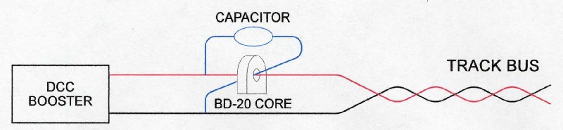
Compensating Twisted Pair Buses for Reliable Block Detection The following was contributed by John M. Smith, jmsmith87@earthlink.net Track wiring capacitance can cause a NCE BD-20 to indicate that the track is occupied, when it is not. A capacitor, connected as shown here, can compensate for the capacitance of the track wiring, and allow the BD-20 to operate normally.
The capacitance connections are critical. For discussion, in this figure the bus wire that passes through the BD-20 core is colored red, and the other is colored black. Make a connection from the bus red wire to one terminal of the capacitor. This connection must be on the same side of the core as the booster, as shown. Current through this connection to the capacitor must not have gone through the core first. Connect a wire to the other terminal of the capacitor, pass it through the core in the direction opposite that of the red bus wire, and connect it to the black wire (anywhere nearby). The capacitor value is not critical. For a 21-foot track bus of twisted 16 AWG wires, compensating capacitors ranging in value from 62 pF to 1000 pF were effective. A 390 pF was chosen. Use a non-polarized capacitor!
INFORMATION #10-10: Cheap and Dirty, Crude, Cheapskate Block Detector.First, let me say that I am not proud of this detector. It violates at least one design rule. Yet it works. A year after its creation, none of them have burned themselves up for violating that design rule. What you have is probably the cheapest block detector you will find. You can probably build it for $0.50. This was designed for a friend who wanted something simple to indicate trains on his hidden storage tracks. He didn't want it to feedback to a DCC system. He just wanted a cheap circuit that would light an LED. It is simple and it is crude. All it does is light one or two LED's on a control panel. Heck, if you wanted to, I suppose you could light three or four. It is not sensitive. Normal resistors on wheels, in the 5k ohm or higher range won't work. If you want to detect cars, you will need resistors less than 1k ohms. Less than 100 ohms will be better. Otherwise, you won't see the light on the control panel very brightly. The resistors will need to be 1/2 watt. Obviously, all these low value resistors could add up to be a significant load on a booster. Therefore, other than detecting your locomotive, I would only put resistors on the wheels of your cabooses, or better yet, light the caboose. This detector, being crude, will cause a 2.8V drop on your track. A train going from a block using this detector to one that does not, will noticeably speed up. A train will noticeably slow down when leaving an undetected block to a detected block. As cheap as this detector is, you could block detect all blocks. The change in speed is noticeable, but you may decide it is tolerable and not worth worrying about. Build a few of these detectors and try it. If you don't need an indicator for every block, but don't want the speed change, you can leave off the LED's. In this case, the circuit just acts as a voltage equalizer. For a super cheap circuit, my friend uses a 1A diode, like the 1N4001. This will work for HO, N, and Z. If HO, do not run multiple units. You may blow the diodes. For multiple lash-ups or larger scales, use a 3A diode. However eight 3A diodes can cost so much, you would be just as well off to buy a normal block detector. Lastly, this simple circuit cannot feedback into a DCC system. To make it do so, would add cost. This thing isn't worth it for that. Buy a normal block detector. THIS IS SIMPLY SOMETHING THAT IS CHEAP AND DIRTY FOR THOSE THAT DON'T NEED ANYTHING SPECIAL AND CAN LIVE WITH THE LIMITIATIONS. I can't promise this will work for everyone. If it works for you, enjoy!
INFORMATION #10-12: Equalization between Detected and Non-Detected Blocks. Many block detectors use diodes in series with the DCC signal going to the track. This isn't the ideal way, because it introduces a voltage drop to the track, but as the above cheapskate detector demonstrates, it is a cheap way of doing it. I designed the cheapskate detector for a friend who didn't need feedback to a computer system. I do want such feedback. I use a more sophisticated detector, but it still has a diode in series with the block. I don't detect my industrial sidings and yard tracks. So there is a voltage change when going from a detected block to a non-detected block or back. It's not as bad as with the cheapskate detector, but it is there. For other than the cheapskate detector, the difference is only about 0.7V. This might not be noticeable to you. Or you may not find it objectionable. I don't. If you run lighted passenger trains, it might be easier to notice. You still might not care. If you don't notice the difference or don't care, do nothing — you are done! Stop here! The following is for those who notice the difference and care.
This first approach is useful when you only have and want one track bus under any particular area of your layout. The diodes should be 3A, 25V minimum rating. Yes, my friend's cheapskate detectors continue to work fine with 1A diodes. I still attribute this more to good luck and him running small trains. Large trains or multi-unit lash-ups would certainly take out the 1A diodes.
Use at least 3A, 25V diodes for this — a higher amperage rating if you are using a 5A booster. The diodes should be able to handle more than the booster can put out. This approach uses fewer diodes overall. You do have to run a second bus. In the end, this may not be cheaper, but not having to put together a bunch of diode pairs will make it faster. You don't actually have to use two different boosters. The diode pair shown on the left could be "t'ed" off the "A" terminal of the booster on the right.
Block Detection Made Easy Railnet offers easy to install block detectors that are also easy to set up. http://www.RailnetSolutions.com
Setting Up a Digitrax DS-54 for Block Detection How to set up a Digitrax DS-54 is discussed in the section on Turnout Control. You can either use the DS-54 for detecting 8 blocks or 4 blocks and 4 turnouts. The CV configuration is the same for either approach.
Using Twisted Bus Wires or End Terminators See discussion in track wiring section.
If you are using twisting or end terminators, you must put your
block detectors after the twists and end terminators.
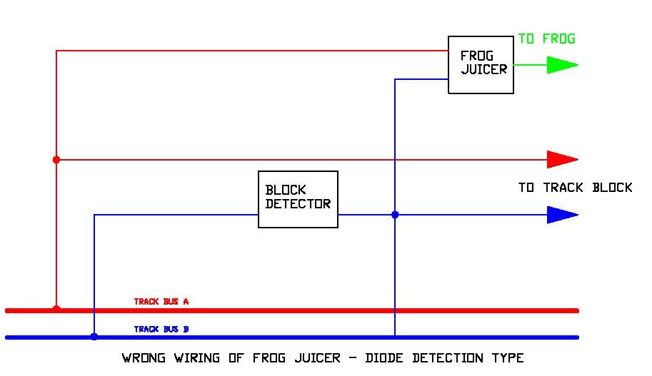
Using Frog Juicers with Block Detection This section only covers the use of frog juicers with block occupancy detection. For more on what a frog juicer is, what it offers you, and wiring to your track, see the discussion on frog juicers in the section on Turnouts. This is a really cool product. If you are not familiar with them, be sure to check them out! Frog juicers need a little bit of power to operate; even when a train is not going across the frog it is connected to. This means that if wired after a block detector, your block detector will see the block as being occupied. So that this does not happen, you will need to wire your frog juicer before the block detector, not after it. The following diagrams will make my point clear. (At least I hope so. I'm really an optimist!)
The above diagram shows a frog juicer wired after the block detector (wiring shown in blue). This will cause your block detector to indicate the presence of a train. You do not want to wire your frog juicer this way. There are two general types of block detectors. One uses diodes. Digitrax uses this. The other type uses current transformers. If you don't know what type you have, here is how you can tell: If yours has a hole that you pass the bus wire through for detection, this is the current transformer type. Otherwise, you have the diode type. In a moment, I'll explain why it matters which type you have.
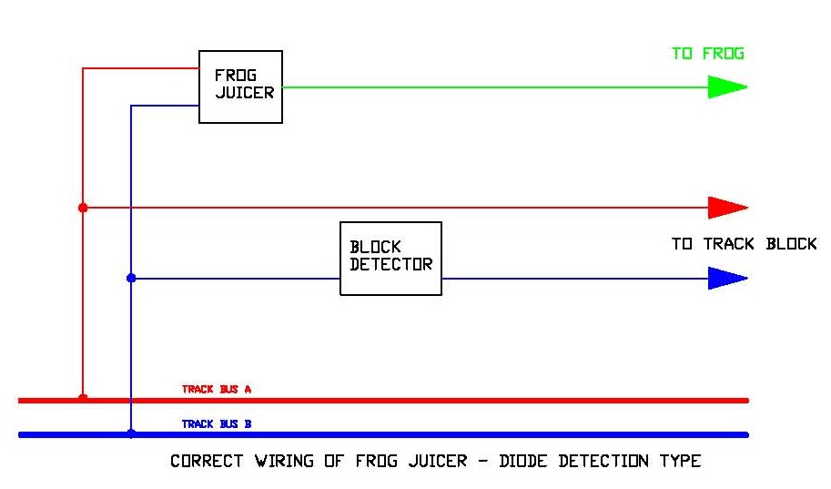
If you are using the diode detection type, then the diagram above shows you how to wire your frog juicer. It must be connected to your track bus before the block detector as shown. As you might suspect, a locomotive drawing power only from the frog will briefly not be detected. This may or may not be an issue for your signalling software. If your locomotive has multiple wheel pick up, you are using multiple locomotives in a consist, you are using lighted passenger cars, you have a lighted caboose, or you have installed resistors on the wheels of your cars, you will not likely experience a problem.
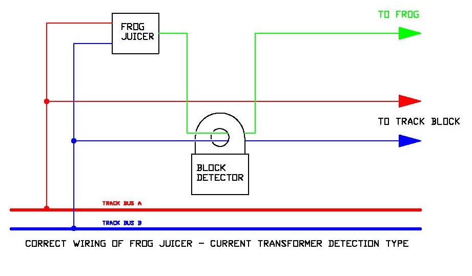
If you are using the current transformer type of block occupancy detection, you still have to wire it before the detector or avoid false occupancy, but you can wire the frog juicer through the block detector to obtain occupancy indication even when passing over a frog. Note that when the frog juicer is set for the diverging route, this may not work with all current transformer block detection systems. Have no fear, it won't hurt anything. You just may not get an indication of block occupancy over the frog. Note: In case you are wondering, now that current transformers are inexpensive, modellers generally prefer this type of block detection because it does not cause a voltage drop on your track like diode detectors do. Block Detection, Frog Juicers, and Power Routed Turnouts If you are not using frog juicers (Made by anyone, not just Tam Valley. I'll just call it a juicer. I am refering to all devices that electronically power route a frog.), you don't need to read this. If you are not power routing your frogs in any way, like using insulated frogs, you don't need to read this. If you are using Tortoises to power route frogs, you don't need to read this. If you are not doing block detection, you don't need to read this. You can stop now. If you are using a diode type block detector, keep reading. You can use this information below. I wanted to build a layout that I didn't have to crawl under to install switch machines and I like power routing turnouts for locomotives that don't have all-driver pick up. I decided to go with manual, power routed turnouts using juicers. I also opted to use the current transformer type of block detector. As described above, juicers draw a little bit of track power and would activate a block detector if it came after it. Above I show you how to use a juicer with a current transformer block detector. When I started building my layout, I had a siding I wanted to block detected that had three juicers I would have had to run their wires through the current transformer including the track itself. That would have been four wires through that coil transformer. Suddently, the hole through the current transformer was looking very small! Note while I use stranded 14 AWG wire for my buses, I use solid 18 AWG running through my current transformers. The 18 AWG puts less strain on the current transformer. I run the 18 AWG to a terminal strip that I attach the 14 AWG wire if the destination of the feeder is more than 4 feet away. See my feeder wire experiment in the track section for why feeders that are 18 or 20 AWG can't be more than 4 feet long. Sometimes, the distance from the juicer to the turnout was more than 4 feet. Or, if I chose to locate the juicer closer to the turnout and far away from my electronic circuit breaker, then I had to run heavy wires from it to the juicer. If you don't, your wiring may fail to shut down your booster or electronic circuit breaker - the famed "quarter test." Here's one that will get you. You might be tempted to use 16 AWG because it is easier to work with than 14 AWG. You can buy 16 AWG stranded from hobby suppliers like All Electronics, but not 16 AWG solid. That''s fine, most people like stranded. But if you want 16 AWG solid, you have to go to places like Digikey or Mouser. I like them, too, but wire is MUCH cheaper from hobby suppliers like All Electronics or Jameco. In the case of 16 AWG, Mouser wants $80 for a 100 foot roll! Ouch! In comparison, I bought 500 feet of 14 AWG from Lowes for $45. So either use 16 AWG stranded or 14 AWG. I gave up on block detecting the frogs on my turnouts. I put the juicer ahead of the block detector as shown above. I did not run the output of the juicer ahead through the coil of the current transformer. So for ever litte bit of turnout that was powered by a juicer, I did not have detection. I haven't hooked into a signalling system yet. I'm still building. I may revise this after I do implement signalling. But so far, with all wheel pickup diesels, the block detectors are not going dark when the wheels are on the frog. So far, so good! BUT, as you wire, you need to keep your wits about you. You may end up breaking your sub bus into two parts. You need to always remember that your juicer needs to come before your block detection. When you wire your turnout, the non-detected juicer wire to the frog needs to come separate from the feeders to the turnout itself - which does go through the current transformer. If you only have one, or maybe two, juicers associated with a block, you can still run it through the current transformer. I didn't run any of my juicers through the current transformer to be consistent. If all of this is giving you a headache, as well it might, then either use insulated frog turnouts (no power routing) or switch machines with built-in mechanical switches (like Tortoises) to do your power routing. Finally, for users of diode block detectors like those made by Digitrax, you don't have to snake a wire through a transformer, but you have the same issue that the juicer, if used, has to come before the detector. So the more complicated wiring is still needed. |
Copyright by Allan Gartner 1996 - 2024 © All rights reserved. All trademarks are property of their respective owners. You may print this for your own, personal, non-commercial use. Non-commercial, non-personal reproduction may be requested by visiting www.WiringForDCC.com/writeme.htm. All users, commercial and non-commercial, may link only to this site at www.WiringForDCC.com. Thanks to all who contribute to this site and the Q&A forum! |
 I
believe Xylene is a carcinogen. Use outside if you must use it!
I believe "temperature steadily" means it might burn if it reaches 392
degrees Fahrenheit so you should heed the advice of keeping it away
from fire and heat sources that might ignite it.
I
believe Xylene is a carcinogen. Use outside if you must use it!
I believe "temperature steadily" means it might burn if it reaches 392
degrees Fahrenheit so you should heed the advice of keeping it away
from fire and heat sources that might ignite it.