Turnouts
|
||||
Turnouts |
||||
INFORMATION 8-1: Decoder Wiring Colors The NMRA recommended practices that define the colors and functions of the wires attached to locomotive decoders. So when you follow my diagrams below, you may use any decoder made by any manufacturer you choose. Borrowing from the NMRA
DCC wiring Recommended Practices, RP-9.1.1, the colors and functions What is a "motor brush?" Internal to the motor is a part called the brush. The two wires or terminals on the motor go to the brushes inside. The brushes couple the power to the rotating portion of the motor called the rotor. What is a "power sink?" The term "sink" is difficult to explain in a few sentences clearly. Suffice it to say, outputs that turn something on by grounding them are "power sinks." The important thing is that the device turned on must be tied to power somewhere. In our decoders this power is supplied by the blue wire. SUGGESTION 8-2: Leaving Steam Locomotive Headlights Grounded. You have the option of operating your headlights at full brightness. To do this, you must use the blue wire. However, many steam locomotives have metal bodies where one side of the headlight is grounded to one of the wheel sets picking up power. You may elect not to use the blue wire and leave the headlight grounded. It will operate at half brightness. I found this unsatisfactory. Trying to isolate the locomotive's original headlight bulb from ground may be impossible or nearly so. Full brightness is easiest obtained with a grain of wheat bulb. RECOMMENDATION 8-3: Replace Your Headlight With a Grain of Wheat Bulb. This is probably easier in a lot of cases than trying to isolate your head light bulb as described for the Big Boy below. It's also the way to go if you want full brightness, rather than half brightness. The grain of wheat bulb has no metallic contacts and therefore doesn't require any effort to isolate it from your engine's chassis. Also, you don't have to fiddle with the locomotive's electrical contacts for its existing headlight. I have found these somewhat hoky in some cases. I like bullet-proof dependability. So if you find that you are spending too much time fiddling with the existing headlight arrangement, you may want to consider grain of wheat bulbs. If you need more motivation to consider grain of wheat, I think it was one of these hoky arrangements that fried a headlight output. I suspected a short occurred during operation. SUGGESTION 8-4: Use LGB 24V Light Bulbs for your G scale locomotives. Many G scale locomotives use voltage regulators and low voltage lamps so they achieve full brightness before the locomotive is moving much. For example, LGB uses 5V lamps and regulators and Bachmann uses about 8V. With DCC, you don't need the voltage regulators. Keeping them means you spend a lot of time figuring out exactly how it is hooked up and works. You also may not be able to take advantage of all that DCC has to offer if you keep the voltage regulator. Toss the voltage regulator and the low voltage lamps that came with your locomotive. Just use the LGB 24V lamps with your DCC decoder. It's that simple! In case you didn't know it, DCC puts a constant voltage on the track that makes the 24V lamp appropriate. The LGB part number is 68513.
Properly Installed Decoder That Won't Work at All. Decoders with Improper
Factory Default Address. If you installed a decoder and are sure you did it correctly, but the locomotive doesn't run on the factory default address, maybe it came programmed to the wrong address. Digitrax, for example, preprograms their decoders to address 3. I had one that was on address 0. Fortunately, with the Digitrax Chief and their decoders, you can read the address from CV#1. Be sure to check this before returning a seemingly defective decoder. This minor problem is not limited to Digitrax. I have gotten reports on other manufacturer's products that have also not had the advertised address preprogrammed into them. Fortunately, this isn't a big deal to fix. We should all be testing our decoders before installing them into a locomotive. If we didn't, we all deserve the sinking feeling we get when it doesn't work at all! It's easy to build a decoder tester using speaker spring terminals from Radio Shack and some more resistors and LEDs. Locomotive Runs Slow or Poorly If your locomotive is running slow or not at all, resist the temptation to turn up the voltage on your track. In other words, if you have an N-scale locomotive, don’t set your booster to G-scale. This never fixes anything, frequently makes things worse, and does not provide any useful information to people like myself who are trying to help you resolve your problem.
SUGGESTION 8-6: Do an Incremental Installation. After testing your decoder, install it in the locomotive enough to get it running. That's 4 wires. Then hook up some grain of wheat bulbs and test the headlights. Yes, if you properly tested your decoder in the first place, you should be able to expect everything to work. Look at it this way. It only takes about 30 seconds more to do this. And isn't this better than doing the whole job, screwing everything back together, and then finding out something is amiss??? If you can, hook up the actual head lights and test them, too, before screwing everything back together. TROUBLESHOOTING 8-7: Head Light Doesn't Always Work. If this is your first locomotive and your head light doesn't work or it does some of the time, don't panic. Your decoder probably has directional lighting and your locomotive may be set for reverse. RECOMMENDATION 8-8: ALWAYS Ensure That Neither Motor Lead is Grounded to Your Locomotive's Frame That's right. Don't trust me. If I say that the motor in a particular locomotive is not grounded to the frame, don't believe me. Who knows for sure that the motor that came with your locomotive is the same as the one in mine. If you have a different motor, your decoder could be destroyed. So always check that neither motor lead is connected to your locomotive's frame. Do this by connecting an ohm meter between either motor lead and try every wheel. Then do the other motor lead and all the wheels. Note: The motor frame in all likelyhood is connected to your frame. This isn't a problem. It's the leads to the motor, the ones you will soon attach decoder wires to, that are your concern.
Get Yourself an Ohmmeter for Installing Decoders It is almost impossible to install a decoder into a locomotive without an ohmmeter. An ohmmeter is usually incorporated into a device frequently called a multimeter or digital volt meter (DVM). An analog multimeter (p/n 22-218) – one with a needle – is available from Radio Shack for $15.99. A DVM (p/n 22-810) is just $19.99. If you can afford a decoder for your locomotive, you can afford one of these meters. Let me put it another way, if you can afford to not have one of these and then "let the smoke out" of a decoder, you can afford one of these meters. Once your purchase the meter, use the lowest ohms setting to determine if your motor is isolated from your frame and from your pick-up wheels. Also use the ohmmeter to trace out the wires – to figure out which is which and where it goes. Finally, use it to figure out which wheels are being used for power pick-up. Like I said, it’s hard to install a decoder in a locomotive without one of these meters. For more on using one of these meters, read the section on “General Decoder Installation Instructions.”
General Decoder Installation Instructions It is difficult for this website to help you with your locomotive decoder installations. This is because I don’t have your locomotive. It is not in front of me and I don’t know what is in it or how it was put together. Fortunately, decoder installation really isn’t hard. On this website you will find installation instructions for numerous locomotives. If you don’t see your locomotive listed, these step-by-step instructions below should get you through the project. Before you start. If you have an analog ohm meter, you must “zero” the meter each time you use it and after you change ranges. This is done simply by shorting the probes together and rotating the adjustment dial until the meter reads zero. Note that the ohms scale starts on the right side of the meter. You don’t have to zero a digital meter. However, you will find that a digital meter never reads zero. Typically it will read 0.4 to 0.6 ohms. This is normal. There is nothing wrong with the meter. These are general decoder installation instructions intended for older locomotives that have no electronic components inside of them or somewhat newer locomotives that may have a few electronic components in them, but do not have an 8-pin connector in them for a DCC decoder and probably were not intended to be DCC ready or were made prior to DCC. There are three phases to installing a decoder in a locomotive. I. Figure out how the locomotive was wired. I. Figuring out the locomotive’s existing wiring. Locomotives that have no electronic components are all wired the same way. The headlight is wired in parallel with the motor. One side of this parallel combination will probably be connected to the chassis if it is metal. This in turn will be connected to some wheels for power pick-up. You can confirm this by using your ohm meter. Touch all your wheels, including the tender wheels with one probe of your ohm meter. Attach the other meter lead to one of the leads on your motor. If you do all the wheels without moving the test probe on the motor, you should get two sets of readings. One set of readings will be from the motor lead directly to the wheels. The other set of readings will include the resistance of the lamp and motor. Don’t panic if you can’t tell the readings apart at this stage. If you figure out which wheels you are getting power from, you are doing fine. Note that some locomotives may be using tender wheels, in addition to or instead of, driver wheels to pick up power. Disconnect at one wire going to the motor. Check with your ohm meter and determine if that wire is going to the “engineer’s side” (right side with loco facing forward) or “fireman’s side” (left side with loco facing forward). Note this for later. If you will have to take the motor out and may rotate it, put a mark on the motor so that you know which terminal the removed wire went to. II. Disconnect everything in the locomotive. If the locomotive has any kind of electronics in it (but was not purchased “DCC ready”), you will be removing them. This includes directional lighting, constant lighting, mars lighting, and electrical noise filtering circuits. If the headlight is connected to the chassis, remove headlight and replace with a grain of wheat bulb (for HO) or a grain of rice bulb (for N) in series with a 680 ohm resistor (Radio Shack p/n 271-1117). Do not connect any headlight wires at this time. Disconnect both wires going to motor. If only one wire is going to the motor, than the motor is connected to the chassis. Even if you have two wires going to the motor, after disconnecting the wires, use your ohm meter to ensure neither motor terminal is tied to the chassis. Check and see if the chassis also connected to wheel pick-ups. You must isolate the motor from the chassis! Use your ohm meter to ensure that the motor is isolated when you are done. This is important! If you don’t do this, you will likely “let the smoke out” of your decoder. Once you let the smoke out, electronic devices never work again. With the headlight and motor disconnected, you should now be able to use your ohmmeter to conclusively determine which wheels your locomotive is using for electrical pick-up. III Installing the decoder. 1. Connect the red decoder wire to the “engineer’s side” (right side with loco facing forward) wheel pick-ups. 2. Connect the black decoder wire to the “fireman’s side” (left side with loco facing forward) wheel pick-ups. 3. Temporarily connect the orange decoder wire to one of the motor leads. If you noted which of the wires that were going to the motor were from the engineer’s side, attach the orange wire to the motor lead that you previously identified as the engineer’s side. 4. Temporarily connect the gray decoder wire to the other motor lead. 5. Very important! Test your locomotive on address #03. It should move smoothly and in the direction set on your throttle. If it does, you can permanently attach the gray and orange wires. If the locomotive goes in the wrong direction, reverse the orange and gray wires before permanently attaching them. 6. Connect the white decoder wire to one wire of your headlight (or to the resistor if you are using a grain of rice bulb). 7. Temporarily connect the blue decoder wire to the other wire of your headlight. 8. Very important! Test your locomotive. Function 0, with the locomotive commanded to go forward, should light the headlight. 9. Connect the yellow decoder wire to your rear headlight. Or connect the yellow wire to a resistor if you are using a grain of rice bulb. 10. Temporarily connect the blue decoder to the rear headlight. 11. Very important! Test your locomotive. Function 0, with the locomotive commanded to go in reverse, should light the rear light. 12. Your decoder may have other wires that control functions. Hook them up to your mars light or whatever as if they were a headlight. Be sure to install a 22 ohm resistor in series with any light to be used as a mars light, flashing, pulsating, or gyrating light. If you are using a grain of rice bulb and a 680 ohm resistor, you do not need to add the 22 ohm resistor. 13. Make all your temporary connections permanent and you are done!
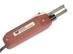
SUGGESTION: Locomotives with Filter Circuits The following was contributed by Mark Gurries Many locomotives seem to come with some filtering electronics for the motor. This filter circuit often consists of a ceramic capacitor and one or two stick inductors. It exists because some locomotive manufacture are attempting to reduce the "Radio Wave" interference the motors can create when they run. Think motor noise & static noise you get on the TV or Radio type of thing. They add this filter to reduce the interference to comply with some regulation agency that regulates such things. To be clear, most locomotive manufactures have NO filter circuit at all. The filter circuit was intended to be used with the engine while operating in DC mode as opposed to DCC. As people have found, DCC decoders were not designed to work with these filters. In many cases it has lead to erratic operation. The recommendation is that for DCC, at a minimum the capacitor should be removed completely (clipped out). Removing the whole filter is required if you use a decoder with BEMF (back EMF, load compensation, or speed compensation). SUGGESTION: Thermal Wire Stripper for Delicate Decoder Wires Decoder wires in particular can be delicate. So can wires in your locomotives. Sometimes your wires are very short. When stripping any wire you need to be able to hold onto the wire and pull on it rather forcefully. For delicate and short wires, you can't grip the wire and you might break off the wire. For these cases, you need a thermal wire stripper. Unfortunately, the reasonably priced thermal wire stripper I posted here many years ago is no longer available. I've seen several on eBay. You don't need anything fancy. Buying the cheapest one is fine.
The one I have is shown above. It is the Teledyne; now DMC. It looks simple, but a new one is now about $585 from Mouser Electronics. It's Mouser part number is 654-TW-1. https://www.Mouser.com. I paid much less for mine many years ago. It might not be cheap, but it still works great.
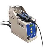
I also found one that is less expensive at $438 and looks fancier. It is shown above. It is available from
Hisco. https://www.hisco.com. The Hisco part number is FT802-03-3021. Note that you will need to buy a blade; available seperately.
INFORMATION 8-9: Where to Get Decoders Installed. No, I don't install decoders as a service. I have my hands full trying to maintain this page! There are a number of people who will install decoders in your locomotive for a very reasonable fee. They advertise on my home page.
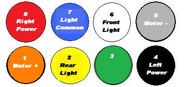
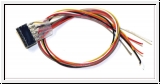
INFORMATION 8-10: Locked Rotor Stall Current. One manufacturer defines stall current as the locomotive stopped and the wheels spinning. Others specify it as wheels being held from spinning. This means the motor shaft is not rotating. When a motor shaft is kept from spinning, it is called a locked rotor. This is the highest current the motor will draw. This is worse, or more conservative, than the current reading that will be obtained when the locomotive is held in place with the wheels spinning. Therefore, I will report the locked rotor stall current. You won't go wrong if you select a decoder based on this. Suggestion 8-11: Use Plastic Couplers on Locomotives with Metal Chassis or Bodies. There are now plastic knuckle couplers by several manufacturers. McHenry, Intermountain, Accurail, and Kadee. Kadee's #30 is the same as their #5, but plastic. The reason is not obvious. It becomes apparent with cars that have metal couplers. The chassis of the locomotive may be common to one rail or another. The coupler trip pin can contact a rail when crossing a rail switch or crossovers. Brass cabooses with lighting or passenger cars are obvious sources of trouble. In the case of lighted cars, it is easy to say ensure all your hot chassis rolling stock and locomotives are attached to the same rail. I don't know that this is an attainable goal. I have been told you can use the #30 Kadee's on the Proto 2000 FA2. Just because a locomotive has a metal chassis or body, doesn't mean that it is common to either rail or either motor lead. Don't leave your motor leads common to your chassis! Installing any decoder, you know this already. I'm also told the Spectrum Fairbanks Morris H16-44 or E-8 don't have this hot chassis problem. I have an E-8 that I plan to put a decoder in so I will have to check this out. I'll start checking for this as I do decoder installations. INFORMATION 8-12: Using a Zimo Decoder. I use the Zimo MX65 series of decoders for my G-scale locomotives because they have back-emf control (feedback, load compensation, speed stabilization, or whatever a decoder manufacturer wants to call it.) They can be ordered from The Train Connection. Unfortunately, it does not have special effects like Mars light, strobes, etc. useful to US modelers. It also does not have flickering firebox effects. Fortunately, most G-scale locomotives have this already built in. Flickering firebox is also built into the Soundtraxx products. These decoders have a ribbon cable connection. But the ribbon cable does not come with the decoder. You can order the cable you need from Digikey. The part number is C3AAT-1618M-ND . It is a multicolored, 18"ribbon cable with tin plated contacts for $3.69. Cut this cable in half and you will be able to do two Zimo decoders. Since you will mate this connector one time and leave it alone inside the locomotive, you don't need higher grade connector. Should you want one anyway, a gold plated cable is $4.24; part number C3AAG-1618M-ND. Note: Ribbon cables will fail if it is flexed a lot, handled often, or if strain is placed on the cable. Strain is particularly important to a cable that is inside a locomotive. Be sure there is no strain on the cable. It will fail eventually — and probably a lot sooner than either of us wants! For the ultimate ribbon cable with strain relief, Digikey sells a gold plated connector with strain relief for $2.05; part number CSR16G-ND. This is a single connector only. The last thing you should know about the Zimo decoders is their non-standard numbering system for functions. Zimo does not follow NMRA standards. Their functions are labeled one higher than the corresponding NMRA function. Example: NMRA function F3 is Zimo function F4. This does not affect how you use your locomotive once a Zimo decoder is installed. It only affects how you wire it up. If you want the F3 button on your throttle activate a feature in your locomotive, you have to wire it to the Zimo F4 output. Pin #1 on the ribbon cable is the upper left pin when holding the decoder so the ribbon cable connector is on the right. How do you know which wire coming out of the ribbon connector is #1? Stick a small diameter wire into the hole on the connector that corresponds with the upper left pin. Use an ohm meter or digital multimeter to find continuity (reading 0 ohms) between the wire and one of the wires on the ribbon connector. Important Note: Do not force a large wire into the connector or you may damage the connector. Use one that gives you a snug fit only and nothing more. INFORMATION 8-13: Locomotives with Connectors. Some locomotives have this connector wired wrong. So look for a pin 1. If you are to wire up your own harness, here are the NRMA colors that should be connected to the appropriate pins. Again, watch that pin orientation!
Miniature Connectors This section is dedicated to miniature connectors useful for interconnecting steam locomotives with its tender or diesel A-B units. If you have a favorite connector, write-me for instructions on sending me your photos and information.
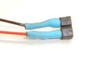
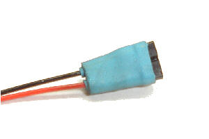
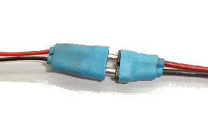
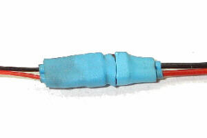
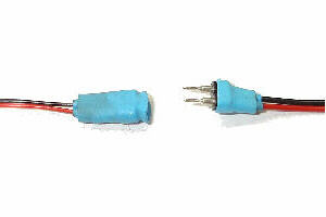
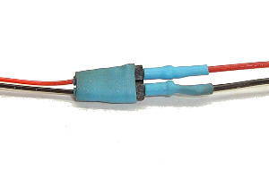
Mini Connectors from Micro-Mark
I recently picked up these connectors from Micro-Mark, http://www.micromark.com. They are two terminals with red and black wires. The connectors are polarized — which means you can only plug them in one way. This enables you to paint everything black and still be able to hook them up correctly. You get 10 male, 10 female, and some heat shrink tubing for $12.95. Part number is 83858.
Mini Micro Connectors from Soundtraxx
These are about the smallest connectors I have run across. They are just a pin and a socket. To make the socket the smallest it can be, you solder the wire to the side of the socket cup. Unfortunately, I've misplaced my unused connectors and can't take a photo for you. Check back some other day for when I find them. These connectors are available from Soundtraxx dealers. The part number is 810058 and lists for $9.00 for a pack of 10 pairs of connectors. Soundtraxx also sells a 2-pin micro connector for $3.50. Its part number is 810012 . I have never used these so I can't tell you any more about them.
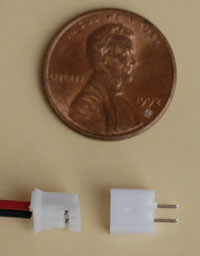
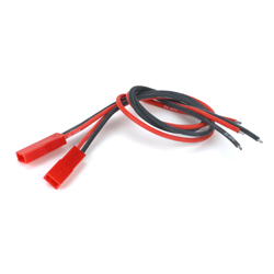
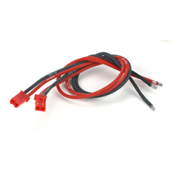
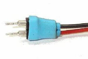
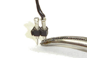
JST Connectors from Advantage Hobby
These female and male connectors are available from Advantage Hobby.com . The female connector part number is EFLA243 and sells for $2.99. The male connector part number is EFLA242 and also sells for $2.99.
NMRA Connectors from Litchfield Station
Litchfield Station sells the 6-pin NMRA plugs, the 8-pin NMRA plugs and sockets, and 8-pin sockets with leads. Visit http://www.litchfieldstation.com/xcart/home.php?cat=174 to see all that they offer and pricing.
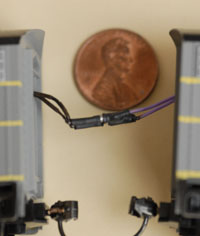
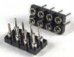
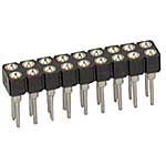
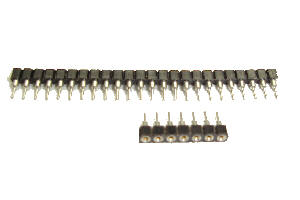
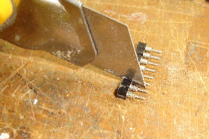
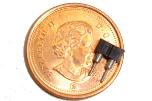
Socket Strips
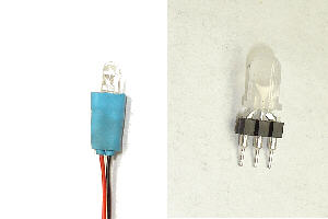
I have saved perhaps the best for last. These were designed to be a universal socket for integrated circuits spaced on .1" centers. Because they can be stacked, they are useful in joining locomotives. They are inexpensive and available from most electronic suppliers, such as Jameco Electronics, http://www.jameco.com , p/n 212898 and Digi-Key, http://www.digikey.com , p/n A208-ND. You can cut these connectors apart and make them any configuration you want. Since they can be stacked, you can use one as a socket and one as a plug. You can also remove the pins from the black molded strips. Care needs to be exercised when soldering to them as the plastic is easily melted. Contributed by Jim Banner Jim Banner, of the Saskatoon Railroad Modelers, shows the versatility of these socket strips. Jim can be reached at sask.rail@shaw.ca or visit his group's site at http://members.shaw.ca/sask.rail.
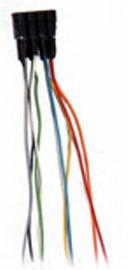
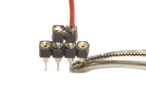
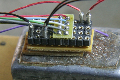
Another application, for which I could not find a photograph, involved epoxying two pin sockets into the ceiling of a wooden large scale building. Then the room lights, fitted with plugs, were plugged into the ceiling sockets. The light fixtures themselves were made from plastic beads turned on an engine lathe and lighted with grain-of-wheat bulbs and warm white LEDs. Doll house applications would be similar. Contributed by Earl Hacket Earl Hackett, who can frequently be found on the Wiring For DCC Q&A Forum, continues to show the versatility of these connectors as he uses the sockets to create a header block where he can plug in a decoder and then plug in the lights, motor, and wheel pick-ups.
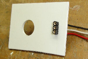
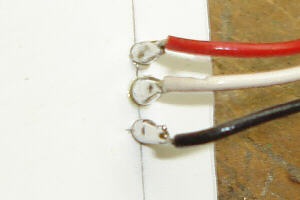
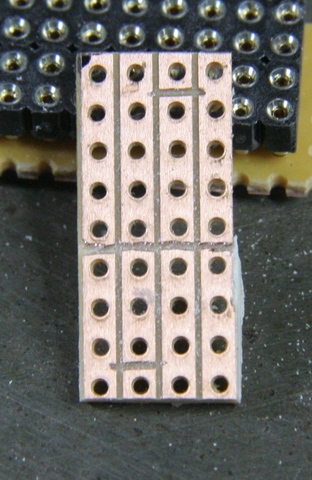
Earl interconnects the pins by using circuit boards that have strips of holes in them.
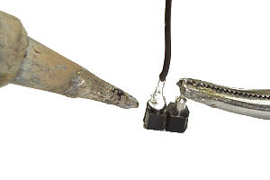
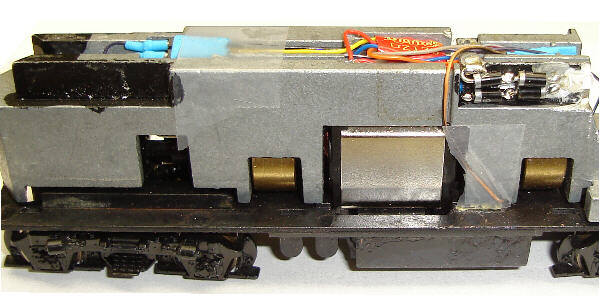
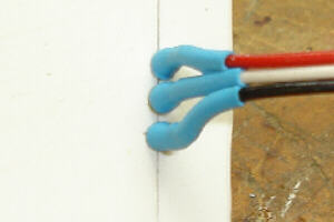
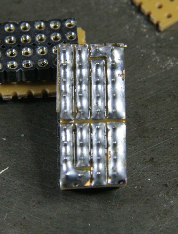
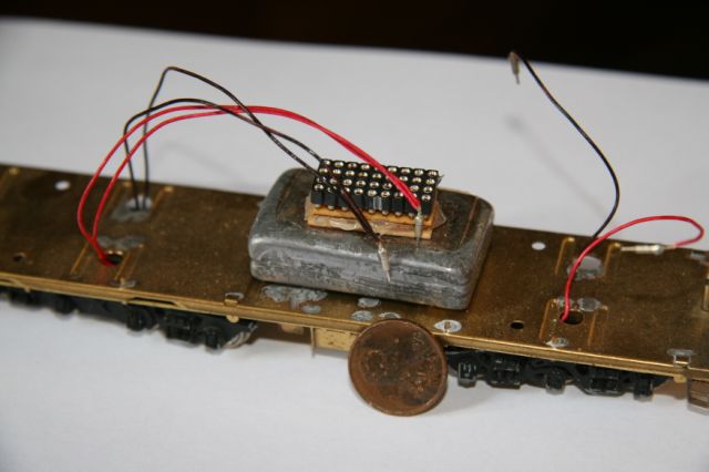
Attached are some photos of a connector made with Jameco PN 212898. A standard NMRA plug attaches where you see the silver mark on the side. The circuit board is just cheap stripboard with the traces cut as needed. In addition to the decoder, this provides connections for two tender trucks, the locomotive drivers (in the case of an articulated, one for each of the engines), and front and rear lights.
The photo of it in the tender also shows the connector pins made from contacts removed from the same connector type.
INFORMATION 8-14: What decoder is right for my locomotive? We get that question a lot on the forum. It is rare that we can answer it. New models of decoders and changes in the locomotives make it impossible. We can't keep up with all the features and combinations of decoders and locomotives. Do this: Try your local store. If they don't know, contact one of the national mail order places that deal in DCC. They get asked this question all the time. They are the ones that know what decoders are currently available. Maybe someone else has already called on the loco you are interested in. If they don't know, they will work with you. After all, they want to sell you and everyone else with that locomotive a decoder! I can tell you that some of the decoders and their harnesses that you can buy are because I went through exactly this process! They will ask you some questions about the locomotive. How big is the space? Does it have a DCC connector? How long does the harness need to be? Then they will make up a decoder that fits. Then it appears on their website as a decoder specific for a particular locomotive. You can certainly try asking on the forum. If that fails, call the people that sell them every day. I don't even bother asking others on my forum. Why? Simple. I need to call and buy a decoder anyway and I want it now — just like you! So call them up, tell them what you want. In a few days, you have a decoder! This is one of those cases where this is simply the best thing to do. Companies that can provide this service advertise on my home page. The hardest part about decoder installation is figuring out what you have after you've opened your locomotive and then deciding how the installation will be implemented. This I have done for you. So the installations should be fairly easy and fast. For all my drawings, the decoders are shown as blue boxes. To make the drawing as readable as possible, I didn't necessarily make the wires all come out of the same end of the decoder. I also didn't necessarily show the decoder in the same place that I actually put it for the same reason. Where to put it will usually be fairly obvious. I will tell you if wires will show under the boiler and that you should blacken them. The decoder and any wires out the cab are your call. I'm definitely not an expert on modeling, so how you do things for the best looking model are up to you. These aren't the definitive way to install the decoders, but shouldn't feel like you are going at this alone and especially alleviate fears of making a serious electrical mistake. If you think of a better way to do something, please pass it along so that others may benefit. Thanks! I don't pretend to be an expert on prototypical operation or appearance. My implementations of mars lights, flickering fireboxes, and such are strictly personal choices. What you get here is a way that will work well electrically. If you try my way but have knowledge that says they should brighter, dimmer, or whatever, please let me know and I will adjust the instruction in these pages as needed. Others will appreciate it! Wanted: Diesel Conversion Write-Ups. Other than an E8, PA-1's, and F-Units, I own no diesels. (This way, I don't lament how much better they usually run!) I realize that most people model diesels. So if you do a diesel conversion, please write it up. Others on the WWW will appreciate it! Out-Dated Write-Ups: Manufacturers are coming out with new decoders all the time. Furthermore, manufacturers obsolete decoders. Hence, many of these write-ups are out of date. It is not possible for me to keep these write-ups up to date. You may only be able to use these write-ups to determine how to take a locomotive apart and where to connect the wires. This is the most useful aspect of these write-ups. This aspect will become obsolete when a manufacturer redesigns their locomotive — a somewhat slower process. "Kit-Bashing" Write-Ups: Don't see your locomotive? You want to put in sound, but the write-up doesn't show sound? Or maybe the write-up contains an obsolete decoder. Look at other write-ups. You may find that you can use portions of different write-ups to achieve your objective. After you are done, if you care to write-up your locomotive, I will be glad to immortalize your work here on this website! All locomotive write-ups are now listed on my write-ups page. If you would like to do a locomotive decoder installation note, please write me.
|
|
Copyright by Allan Gartner 1996 - 2020 © All rights reserved. You may print this for your own, personal, non-commercial use. Non-commercial, non-personal reproduction may be requested by visiting www.WiringForDCC.com/writeme.htm . All users, commercial and non-commercial, may link only to this site at www.WiringForDCC.com. Thanks to all who contribute to this site and the Q&A forum! |