A resistance soldering system will use less solder— you are less likely to have blobs. The best part is avoiding the
melting of ties.
I used regular electronic solder with rosin core flux.
DO NOT use acid flux on anything electrical! I tried using killed
acid liquid flux, but it didn't work any better than the rosin core
solder.
Why don't you need a larger piece of wire? The
all important thing to us is the voltage drop. When you are done,
you will only have about 0.25" (6mm) of wire between your rails.
Even at 10 amps, this will not be enough to require bigger wire.
Feel free to try 16AWG solid wire or larger if you want to, but be careful
not to melt your ties.
Note: Over time, I have adopted a much larger and
more complex shaped bond. Do you need to worry about them being
unsightly? In no time at all they corrode to a dark color.
You definitely don't even notice they are there and will find them somewhat
difficult to spot without conscientiously looking for them. So much
so, that's why they are easy to hit and break!
12' (4m) is a good rule. This is especially true
if you are not using the stainless steel clamps, or are using 18 AWG
wire or larger for jumpers. You have to be careful that during a
heavy short, your jumpers don't get hot. You do want this to be
a trouble-free railroad, right?
18' (6m) would be the limit if using 14 AWG jumpers or
stainless steel clamps. At the longer distance, the voltage drop
across the rail might be noticeable to some.
Longer distances you have to worry about the voltage
drop and the quality of the joints. With a garden railroad, who
wants to be digging up feeder buses to add more feeders? Or fix
joints that have broken or corroded?
I use jumpers and a feeder for every 6' (2m) of track.
I call this extra effort "insurance". It's not necessary.
It's just what I choose to do. I use 14 AWG solid for feeders
because I have a box of it.
I suggest you use at least 12 AWG wire. I use 10
AWG solid. This is a good idea if you have very long runs. In my case,
I have pieces over a 100 feet (33m) long.
What type of wire is a good question. There are
wires designed for direct burial but they are not suitable for garden
railroad use.
Underground sprinkler wire: Solid wire, but much
too small in diameter to carry the necessary currents.
Low voltage lighting wire: Normally, this stranded
wire has its termination inside above ground lights. Stripping
stranded wire and then trying to solder buried feeders to it will ultimately
fail - probably even if you succeed in waterproofing the connection.
Part of the problem is that soldering stranded wire makes it very rigid
and the tiny flexible strands can break off. If you walk on your
track, you are aggravating this problem. If you don't successfully
waterproof the connection, you are certainly doomed to failure.
Buriable "Romex:" This wire, available in the United
States, has a jacket that makes the wire buriable. Cutting into this
jacket and burying it nullifies the jacket's benefit.
Until I find a wire that seems really good, I use heavy
solid wire. The fatter the wire, the longer it will be before it corrodes
through. I can't tell you how many years, but #10 solid should
give you plenty of them. What I can tell you is if you saw how cruddy
my wires look after just a few years in the ground, you would use #10
for everything! I still expect years of good service. What's
appalling is how quickly nature makes them look so old after such a
short time. It definitely drives you to want to be as sure as
you can that they will be there a long time.
While all the feeder connections challenge garden wiring,
properly installed trackwork helps you out. If you put several
inches of stone under your track and your feeder connections are in
the middle of the stone, your connections will not be immersed in constantly
wet soil.
Another thing that you should think about is the wire's
mechanical strength. In short, the thicker it is, the sooner you
will know you hit it before you break it accidentally sometime down
the road.
I suggest you use at least 16 AWG. If you run feeders
to your track every 6', you can use 18 AWG. I use 14 AWG
solid. If I were to do it again, I would use #12.
Another thing that you should think about is the wire's
mechanical strength. In short, the thicker it is, the sooner you
will know you hit it before you break it accidentally sometime down
the road. If you should have a mud slide or something else that
covers the track, you may not see it and may break it before you know
it. I haven't broken a feeder, but I have broken a bond (jumper.)
SUGGESTION 13-8: Use LGB 24V Light Bulbs for your G scale
locomotives.
Many G scale locomotives use voltage regulators and low voltage
lamps so they achieve full brightness before the locomotive is moving
much. For example, LGB uses 5V lamps and regulators and Bachmann
uses about 8V.
With DCC, you don't need the voltage regulators. Keeping them
means you spending a lot of time figuring out exactly how it is hooked
up and works. You also may not be able to take advantage of
all that DCC has to offer if you keep the voltage regulator.
Toss the voltage regulator and the low voltage lamps that came
with your locomotive. Just use the LGB 24V lamps with your
DCC decoder.
It's that simple! In case you didn't know it, DCC puts a constant
voltage on the track that makes the 24V lamp appropriate.
The LGB part number is 68513.

INFORMATION 13-13:
Decoder Selection
For G scale locomotives, I would suggest that you use
a 5A decoder in any two motor locomotive and a 3A decoder in any single
motor locomotive. Decoders should be given as much space as
possible inside a boiler and preferably access to outside air for
cooling. The later is a good objective that you can rarely fullfil.
My real problem isn't the internally generated heat as much
as Texas' 105 degree days. Still, my Sumpter Valley, with its
Digitrax DG580 decoder, ran 1.5 hours before thermally shutting down.
I have three loops on my garden railroad. One has an intentional
7.8% grade for the logging loop. For this steep grade, load
compensating decoders are a must if you have a back yard full of guests
and you don't want to have ride the throttle to get it up the hill
and to keep it from rocketing off a curve coming down.
My Sumpter Valley, on my 3.8% grades of the non logging loops, shows
a noticeable, but not significant, speed change with its non load
compensating decoder. If your steepest grade is about this much
or less, you may be able to get by without a load compensating decoder.
A smaller locomotive, like an LGB Mogul, has to work harder
to get up the 3.8% grade and will therefore go down that grade faster
without load compensation. So, though not essential for a smaller
locomotive, you probably should consider buying a load compensating
decoder. Unless you have tight downhill curves, you should not
have a runaway rocket situation. All lesser grades, you don't
need to buy a load compensating decoder. There is no harm, of
course, in outfitting all locomotives with load compensating decoders
as I am doing.
See the information below on selecting decoders with load compensation
if this interests you.
INFORMATION 13-9: Decoders with "Back EMF",
"Feedback", "Load Compensation", Speed Stabilization"
"Back EMF", "feedback", "load compensation", and "speed stabilization"
are names for the capability of decoders that can keep the speed of
a train relatively constant automatically while ascending or descending
a grade. When I have a back yard full of guests, I have
found this to be a useful feature to have as I cannot concentrate
on watching the trains. This feature can be turned off when
more prototypical operation is desired.
There are only a few manufacturers that have decoders for G-scale
locomotives.
Lenz's has a maximum output of 3.5A and does not support 128 speed
steps. It handles long addressing. It has no special effects.
As of this writing, Lenz has a special dual decoder combination
that has load compensation for use with two motor locomotives.
However, this pair costs as much as two decoders.
Zimo's has a maximum output of 5A, supports 128 support steps, long
addressing, and has no special effects useful to a US modelers. The
MX65 comes in three models, the most advanced of which includes a
1.2V voltage source and a programmable output for controlling sound
systems that use voltage control of their sound effects.
All the MX65's have a computer ribbon cable connector for the lighting
and function outputs. A screw terminal block is used for track
and motor power. You must be careful stripping ribbon cable
wires. Unfortunately, the ribbon cable connector does not come
with the decoder. You can get these from Digikey.
See the section on Parts for part numbers.
Until Digitrax comes out with a G-scale decoder with back emf control
(load compensation, speed stabilization, feedback or whatever a manufacturer
wants to call it), I prefer the Zimo decoders. They can be ordered
from The Train Connection.
See the section on Wiring Specific Locomotives
for more on the Zimo decoder. I have had the misfortune of having
a high infant mortality rate - electronics that fail within the first
few hours of use - with the Zimo's. Fortunately, Carroll at
the Train Connection has always been quick to make good on them.
SUGGESTION 13-10: Using Soundtraxx Sierra Sound Modules with
DCC Decoders
The Sierra has a few features that make it most desirable in a DCC
G-scale locomotive. Besides the best possible sounding bell,
even over their conventional great sounding Soundtraxx product line,
the Sierra offers a number of features that are particularly useful
to the garden railroader. These include magnet triggered bell
and grade crossing whistle, as well as voltage controlled two toots
for forward, three for reverse, and one for stop.
There is an error on the Soundtraxx website concerning the bell,
whistle, hiss, and coupler-clank when hooked to a DCC decoder. You
will notice that the screw numbers don't match their documentation
for the Sierra when used in a conventional DC locomotive.
The Sierra has a feature that detects that your train is in motion,
which way it is going, and when it is stopped. You connect the
Sierra's sense lines to the motor wires from the decoder. To
prevent electrical noise from your DCC decoder from getting into the
Sierra, you will need a filter consisting of the inductor (coil) and
the capacitors shown. Note that when you stop your DCC locomotive
and leave it idle for some time, the Sierra will eventually shut itself
down.
If you do not have a chuff sync mechanism on your locomotive, you
could use another hall-effect sensor and a wheel mounted magnet. Or
you Sierra can generate a chuff based on motor voltage. This
uses the same sense lines that trigger the whistle.
To make the chuff sound more "interesting" in the garden, I discovered
that a chuff rate that is about half of what it really should be is
more entertaining. For a standard, non-articulated locomotive,
there should be four chuffs per revolution. In the garden,
I only use two. Whereas my HO layout is for prototypical operation,
my garden railroad is for entertainment. This is just something
to think about. You don't need to set the chuff rate at precisely
half. I just run the locomotive at what I intend to be its
normal operating speed and then adjust the chuff to suit me.
See the Generic G Decoder and Sierra
Sound Installation in Locomotives section.
SUGGESTION 13-15: Del-Aire for Turnout Control?
LGB switchmachines do not hold up well outside.
They are not designed to be water resistant or to keep out dirt.
They are too weak and don't have enough throw for non-LGB turnouts.
After about four months, it became clear that I would keep buying
LGB's great locomotives but another solution was needed for turnout
control.
I installed Del-Aire "air motors" (actually air cylinders) using
the Llagas Creek G-scale mount. They work like a charm. The
vinyl tubing supplied by Del-Aire is not tolerant of sunlight, so
I found a way to use drip irrigation tubing available in the sprinkler
section of your favorite home improvement store. To use drip
irrigation tubing with your air motors, buy four sizes of brass tubing
from your local hobby shop.
Get sizes 3/32 (#126), 1/8 (#127), 5/32 (#128), and 3/16 (#129).
Cut about 1" long piece of the 3/16. Cut the next size
about 1/4-1/2" longer. The next smaller size another 1/4 -1/2".
The smallest size should be cut about an 1" longer still. So
the smallest size is about 3" long. Wipe each down with liquid flux
and then use a 200W soldering gun and solder one inside the other.
Make sure the solder goes all the way around. When done,
cut the whole thing in half and you will have two Del-Aire to drip
irrigation tubing adapters. DO NOT solder the cut end! Solder
will likely plug the smallest tubing. Take it from someone who
learned this was a bad idea the hard way!
You will need to glue the tubing to this adapter. This adapter you
just created has no barbs on it. When it gets warm, the tubing softens
and the air pressure will blow off either hose. Walther's Goo works.
Make sure it cures thoroughly before applying air or it may blow off
again.
I then cover the Del-Aire tubing with heat shrink tubing. DO
NOT shrink it! I put a big piece of heat shrink over the whole
thing, including the brass tubes and the drip irrigation. This
I shrink lightly, but avoid going tight around the small tubing because
it will easily melt. That's it!
The only drawback in using DCC to control Del-Aire, is that you
will find their electrically operated pneumatic solenoids to be expensive.
(In the industrial automation world, they are actually reasonably
priced.) If you control your Del-Aire air motors with a manual control,
Del-Aire is extremely reasonably priced and MUCH cheaper than LGB
or anything else.
Use the following tubing sizes:
#126 3/32"
#127 1/8"
#128 5/32"
#129 3/16"
SUGGESTION 13-16: Sound Triggering
There are many ways to trigger sound.
1. LGB: The easiest. If only LGB needed our money. They
refuse to sell even LGB owners the bell and whistle trigger mechanism
who own older LGB locomotives that didn't have sound.
2. Reed switches, while very delicate, seem to be the
most sensitive. Fortunately, the ones uses for your home alarm system
are purchasable from Radio Shack. The home alarm system ones are in
a plastic housing to protect the switch. They come in a variety of
styles and you will find at one time or another, you will need them
all. They come as two basic types.
Most are a long barrel. Use a piece of 1x2 lumber cut
to fit under your tender and hold the barrel pointing at the track.
Space for the LGB magnet triggers.
The other general type lays parallel to the track and
you can glue to the bottom of a truck. This is especially useful for
tenders that don't have extra space for a 1x2.
You may encounter one problem with the sensors that are
related to your speaker. If you use a big speaker with a strong magnet,
the magnet in the speaker may interfere with the sensors. I like my
big speaker and found mounting the sensors close to the front of the
tender got them far enough away.
SUGGESTION 13-17: Motorboating / Speaker
Sounding Like a Motorboat
Does your sound system sound more like a motorboat than
a train? Did you use a big speaker? Is it a 4 ohm speaker?
Most sound systems are intended for use with 8ohm speakers.
If you found a nice, big speaker with a healthy magnet on it, it may
be a four ohm speaker. If it is, this is your problem. You are overloading
the output of the audio amplifier.
You have two choices. The obvious is to use a 8ohm speaker.
However, many 8 ohm speakers have very small magnets, are very inefficient,
and don't cover much of the audio range.
Luckily, you can still use your 4ohm speaker and get
most of the advantages. Just put a 4 ohm, 1/2 watt resistor in series
with it. This will bring it up to 8 ohms. Perhaps easier to buy, is
two 1/4 or 1/2 watt, 10 ohm resistors. Put them in parallel with each
other. That makes 5 ohms. Put this pair of resistors in series with
the 4 ohm speaker. The total is 9 ohms. That's good. Yes, this will
cut the amount of power going to the speaker significantly compared
to a normal 8 ohm speaker. But if the efficiency of the 4 ohm is better
than that of a tiny magnet 8 ohm speaker, you are still ahead. Bottom
line, if you find that the locomotive is too loud and you have to
turn it down, who cares if there is an efficiency loss due to this
extra resistors. This is what I have found to be the case.
SUGGESTION 13-18: Sensor Bracket
for Bell and Whistle Triggers.
Until LGB realizes the goldmine they are giving to Radio Shack,
Radio Shack will continue raking in the bucks selling us door alarm
sensors for triggering bell and whistle effects when adding sound
to locomotives; including LGB locomotives. Here is just one way you
can mount the skinny cylinder type Radio Shack sells. The cylinder
will just fit into the hole indicated. It will be barely snug enough
to hold itself in. A little Walther's Goo can be used to hold the
sensor permanently in place. The spacing of the sensors is for the
spacing of the LGB magnets — which they will sell you.
The block of wood is actually used upside down from that shown.
But this is how it will look when you mount it on an upside tender!
The length of the block of wood is not critical. Neither is the
spacing of the holes for the sensors. The groove for the wires is
certainly not critical. I just cut these on my radial arm saw.

Be sure to use safe work practices when using a radial arm saw!
This is the greatest tool ever devised by man for removing fingers
next to the sheer. Be very careful. I suggest you make several of
these wooden blocks at once leaving the long piece of wood to hold
onto and then cut them to their 1-3/4 length. Use a pusher stick when
working on the small pieces. Definitely wear goggles to avoid being
hit in the eyes with these small pieces of wood. If you are using
a radial arm saw, you are responsible for knowing how
to use it safely. I do not pretend to be an expert in the use of radial
arm saws. This website is therefore not a substitute for you knowing
how to use this dangerous tool safely. Read your owner's manual.
The block of wood is a 1x1-1/2 cut in half. Why cut it in half?
Why not just use a 1-3/4 piece of wood? If you don't have a long tender,
you will find a whole piece of wood may hit your wheels.
Funny, after you buy your first LGB locomotive or two, you may find
you need more magnets. After you have acquired a few more LGB locomotives
with sounds, you now find you have enough extra magnets to play see-who-can-get-the-magnet-in-the-gondola-as-it-goes-buy.
No, I haven't been that bored yet, but I do have plenty of magnets!
When done, Walther's Goo the block of wood to the bottom of your
tender with the sensors facing downward. Be as close to the truck
as possible. Note, magnets on curves, particularly tight curves, will
not be sensed in all cases. This is why the truck-mounted LGB bell
and whistle trigger sensor is the ideal choice.
I do not suggest mounting this block of wood directly under your
speaker if you are using a quality, large magnet, speaker as I like
to do. Large magnets on such speakers will interfere with operation
of these magnetic sensors. Hence, my suggestion that you mount it
in front of the front truck if you have problems under the middle
of the tender. Test the sensor operation with track-mounted magnets
and an ohm meter.
Note: Radio Shack sells a flush mount sensor that uses
double-sided foam tape that you can mount on a truck. I've recently
tried that. The truck doesn't have a big mounting surface for it to
stick to. I'm concerned they may not stay mounted without extra glue
or something else. Until I know for sure, you may be on your own.
I had to use these on my Bachmann American which had a tender too
short for this block of wood approach. I'll find out if there is a
problem or not and what the solution is. If you already have encountered
problems with them coming off and found a solution, write me and I'll
give you credit!
SUGGESTION 13-19: Locomotive Cooling.
If you are into diesels, you are in luck. You could use a muffin
fan, for a PC, purchasable at Radio Shack, to circulate air inside
your diesel. If you need a 12VDC circuit, use the power supply circuit
I use for the Sierra sound system. See the locomotive
installation notes on the generic decoder with Sierra sound.
Those of us in Texas with steam locomotives have a serious problem.
I have found even the huge lead weight, on our 100+ summer days, won't
keep a decoder out of thermal overload unless the humidity is very
low (I had locos running at 106 degrees F with 27% humidity. At 47%
humidity SOME decoders would not work). I'd love to mount the decoder
under the locomotive, or even the tender, but there is never room.
I hate running so many wires from the tender.
While this sounds horrible, I now mount my decoders in the cab.
Yes you can see them. Yes there are wires. No doubt, this is not as
pretty as hiding the decoder somewhere. But to be perfectly honest,
I don't think anyone has ever noticed. No modeler has ever asked me
about it. I don't even notice it! Even for me, who is not in awe when
I step into my backyard because I see it everyday, I have too much
to keep an eye on to notice.
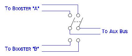
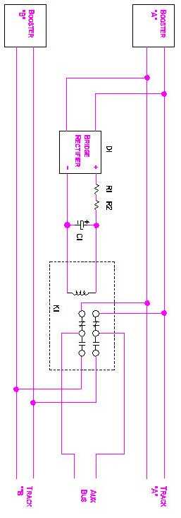
Another choice is to place a switch in a locomotive that allows
it to run on DCC or DC. If the electronics overheats, you can switch
from DCC to DC. You need to do two things. One, is place a switch
in each locomotive that selects the output of a decoder or directly
to the wheels. Then you need a DC power source and place a switch
that selects the DC power supply or the output of a DCC booster.
Here is an example of a locomotive I have wired this way: LGB
F-7A.
So if overheating is a problem, try a locomotive like this. You
may decide this works well for you and isn't as unsightly as it
seems.
They can still get too hot to run, but this the best you can do.
SUGGESTION 13-20: Electronic
Gearing — For Locomotives with More Than One Motor or Two Different
Locomotives.
I hear that the Sumpter Valley and the Unitah run at different speeds.
Some people want to double-head them. Here is how to do it.
I recently had a problem with my Sumpter Valley — an articulated
locomotive with a motor driving each engine (powered truck) separately.
One of the motors, due to age, started running slower than the other.
I found out from the manufacturer that this was not uncommon.
Lesson #1: All locomotives with more than one motor should be placed
on a test stand periodically to check for speed differences. In my
case, I didn't know it until it was too late and I stripped some gears.
The manufacturer recommended I replace both motors at the same time.
That's not an inexpensive solution! And how soon will I need to replace
both motors again?
Enter a technique from my factory automation days. It's called electronic
gearing. This is a process where multiple computer controlled motors
run at different speeds, but proportionally to each other in some
way. Maybe one always turns 90% slower than another. This would be
useful in conveyor control or maybe newsprint going through presses.
It can be easily simulated in DCC using two decoders.
1. Use two decoders. One runs one motor and the locomotive electronics
if it has any. The other decoder simply runs the second motor.
2. Use speed tables. Set up the speed table in both decoders.
3. Use the forward and reverse trim CV's to cause the two decoders
to run at the same speeds. You will probably need to trim down the
decoder that is running fast.
4. Note that both decoders will need to have their own, separate,
address.
5. MU the decoders together so they work as a team.
One new decoder is cheaper than two new motors! In Texas, each decoder
is now working half as hard. This should mean less thermal overload
on scorching hot days.
SUGGESTION 13-21: Virtues of DCC.
Wireless:
I hear true DCC wireless is coming. This is where the DCC signal
is radio'ed directly to the locomotive and the locomotive is running
on batteries. In Texas, keeping the track clean is easy with an old
drywall sponge. So I don't need true wireless. Maybe you don't either.
Be on the lookout for it if you do.
I use standard DCC wireless where the radio signal goes to a receiver.
Commands are then put on the track as in standard DCC. This works
fine for me. Why should you consider it? You can walk your backyard
amongst your guests. You can control trains and throw turnouts even
when the backyard is crowded.
Yes, you can even DCC control your turnouts. This is not inexpensive,
but in a crowded backyard, this is a priceless capability. (I use
DCC to control air valves. I use air powered turnouts. They hold up
to the weather and have more force than the typical outdoor turnout
motor.)
Routing:
This is a feature of some command stations, like the Digitrax Chief,
and/or some stationary address controllers. This is a feature few
modelers employ, but I find particularly useful outdoors and does
not require the use of a computer.
In the dark ages before DCC and twin-coil switch machines, modelers
made something called a diode matrix to control their yard ladders.
DCC has routing. It works without any additional hardware, being all
done in software in either the command station, stationary address
decoders, or a computer if you wish. Using it does not require you
to be a programmer and it can be used for other things besides yards.
I find it particularly useful in the garden because I cannot see
all my turnouts from one place. With wireless and the freedom it affords,
I don't want a control panel.
Routing throws multiple turnouts when I throw a particular turnout.
Just because it throws a turnout one way due to another turnout being
thrown, doesn't mean that same turnout has to be thrown back. The
two are not hard locked together. They work together only when I want
them to. Here's a perfect example:
I have a wye in my garden where I can only see one turnout at a
time. Only in one instance can I see two. Routing allows me to ensure
that the two corresponding legs of the wye are thrown by only throwing
one of them.
When I say they are not hard locked together, here's how I use it.
I have a turnout leaving my garage. The other two turnouts are on
the mainline. When I throw either turnout out on the mainline towards
the garage, the one for the garage responds accordingly. However,
when I throw either out on the mainline back to the mainline, the
one at the garage does nothing.
I also have a five track yard in my garage to store my trains. That
takes four turnouts. I only need throw the turnout for the final storage
track that I want and the appropriate turnouts that need to move to
align for that track do so.
If you have a system that supports this capability, take advantage
of it and use it!
SUGGESTION 13-22: Watertight Heat Shrink Tubing.
J. Reep wrote me and told me the following about a heat shrink that
would seal out water:
"I noticed on your website you mentioned that heat shrink did not
seal to the wire and water would by capillary action enter the splice.
I have been using the 3M EPS-200 adhesive lined flexible polyolefin
(heat shrink tubing). This tubing has an adhesive that melts and seals
the tubing during the heating process.
I have been purchasing the tubing from Allied Electronics in Fort
Worth, Texas 817-595-6455. They do handle mail orders.
This is the part numbers for Allied Electronics.
617-0885 1/8" black 28 pieces 6" long 50% reduction
617-0886 3/16" black 24 pieces 6" long 50% reduction
Hang onto your wallet, the heat shrink is not cheap. If I remember
correctly it was about $15 per package."
I have ordered from Allied and they are great. You should also be
able to order this from most of your favorite electronic supply companies
that carry 3M heat shrink tubing. - Allan
SUGGESTION 13-23: Using Non-DCC Lighted Cars on DCC
This will generally work well. If you have good, clean track and
good pick-ups, it will work very well; perhaps better than when using
DC because the track voltage does not vary! The only thing you need
to watch is the car can withstand your DCC track voltage. I run my
track voltage 18V.
USA Trains™ makes a lighted caboose with a flasher on it. I
have contacted them. This caboose is good for 22V.
Call manufacturers before using a car with electronics in
them! The flasher in this caboose obviously has some electronics
in it. A plain lighted car might have some electronics in
it. Inexpensive ones may not, but the more expensive models may to
make the lighting a little more consistent as the track voltage varies.
(Remember, the car was designed for regular DC usage.) So if you have
any doubt, contact the manufacturer. You could blow the electronics
in the car. Those with just a light bulb, will only blow
the bulb.
SUGGESTION 13-24: Programming LGB MTS Decoders
LGB is now supplying some of their locomotives with MTS decoders.
For the most part, they work on DCC layouts. You cannot program them
with Digitrax equipment in any of the programming modes. It may work
with other manufacturers. Try it. The worst that will happen is that
you will completely screw up the CV's in it! (Okay, that isn't funny.
I didn't manage to alter the programming with the Digitrax system,
but the loco would not work. I did manage to get it back.)
As of this writing, you are limited to 23 addresses. It comes preset
to address 03. I suggest if you do not have an MTS-equipped locomotive
yet, that you not assign these low addresses to any more locomotives
in the meantime.
Assuming you have Digitrax or some other manufacturers DCC equipment,
how do you use an LGB MTS decoder? There are two things.
For Programming:
1. Buy an LGB 55045 programmer. Hook it to a computer serial port,
a AC or DC output power supply (the ones I use for my DCC boosters
worked fine), and attach the programmer to some sort of programming
track or engine test stand. The 55045 is the least expensive way to
program the MTS decoder.
2. Download the latest software to operate the 55045. The 55045 comes
with a CD-ROM. It wasn't the latest and version I have could not program
the locomotive. LGB suggested I go to their website and get the latest.
It is free. I suggest you start this way. Version 4.0 was the latest
at the time of this writing. That will avoid the problem I had.
3. The LGB software appears to gives you a choice of 14 or 28 speed
steps. Maybe some of their decoders accommodate 28 speed steps or
will. My locomotive does not. It would not let me set mine to 28.
You can try it and see what happens to you.
4. The MTS decoder has a mode that locks out analog usage. In my MTS
decoder, locking out analog operation disabled the sound. So I leave
analog operation unlocked.
5. Before you can communicate and program your locomotive, you will
need to set the COM port each and every time you start up
the software. It defaults to no COM upon running the software.
I suspect this is an oversight that they will change.
For Running:
My MTS decoder is a 14 step unit. You have to have a DCC system that
you can set to 14 steps. For Digitrax, it can generate 14 step commands
for specific addresses. You do not have to run your entire system
on 14 steps nor reprogram all you other decoders. I'm sure you are
happy about that!
I have never had to run a decoder at 14 steps before. With the Digitrax
system, I just had to read a page in the manual I passed over years
ago. "Status Editing," as Digitrax calls it, is easy on
the Chief. Best of all, the Chief remembers that you set a specific
address to 14 steps even when the Chief is turned off. So I have only
had to do this once.
If you have not used 14 steps before, you are in for a surprise. Don't
give the throttle a quick twist of the wrist like you may be doing
now. You may go through those 14 steps in a hurry! The locomotive
will leap to life. When you go to stop the locomotive, keep this in
mind. Turn the throttle down slowly or else it may abruptly stop.
You will not be able to control the sound with the normal DCC function
buttons. It makes plenty of sounds and triggers from track magnets.
For me, that is fine. With a backyard full of guests, I don't use
the DCC function buttons on my locomotives that are capable of doing
so.
Additional Impressions of the MTS:
It does have some good features. It has load compensation. The sound
that came with mine is good. Sound is not necessarily a function of
MTS, but I expect all MTS-equipped locomotives will have sound. Of
the four manufacturers of decoders I am running, this one has never
shutdown in our Texas heat.
The only thing I see as an issue is the limited number of addresses.
Hopefully, as they come out with more MTS-equipped locomotives, they
will be driven to change this.
BONUS: Wooden Ties for G Scale
Here is a bonus topic. It's non-DCC. While I am figuring
things out, you might as well benefit from it.
Should you decide that you want to lay your own track,
you may want to make your own ties. You may be wondering if it is
worth your while to make them yourself. I can make 450 in 75 minutes
at a cost of about a nickel each. This is about half-price compared
to commercial ties. I make mine oversize. If you make
them smaller, your cost will be lower.
I talked with a G-scale bridge builder. He recommends
mahogany. It isn't the hardest wood available, but as it turns out,
harder woods don't take preservatives well and therefore deteriorate
faster.
I make my ties slightly oversized. Mine are 7/16" x
7/16"
x 3.5".
This is very close to the prototypical 9" wide. Prototypical ties are 6" thick.
It is convenient to make them square. When ballasted, who knows how
thick they are. When they are not ballasted, they make good bridge
ties. Also, the thicker ties makes them a little more tolerant of
being walked on — which is how I service my hard to reach tracks.
Buying hardwoods is a bit different than typical "dimensional"
lumber from your favorite home improvement store. First, wood is sold
in thicknesses usually from 1" thick to 2" thick in increments
of a quarter-inch. But don't show your ignorance by asking for 1"
thick. Ask for "4 4" or "4 quarter." 1.25"
thick is called "5 4" which is five quarters of an inch
thick.
Hardwoods come in seemingly random widths and lengths.
Also, one of the edges may not be straight. How do you know what
it
cost? Hardwoods are sold in "board feet" which is one square
foot at an inch thick. Luckily, you are not trying to build fine
furniture.
Find a piece about 4-6' long, 6-8" wide, and "4 4"
thick (to make 7/16" ties) for your first project. If you want
to make ties of a different thickness, you may want a different
thickness
board to minimize your waste.
You will also notice that the wood comes with finished
sides and coarse sides. The finished surface wood does cost more.
It will still make ties for a nickel. Buy the finished or the rough
surface. After sawing up the wood, I just put the rough surface down.
Set up your table and/or radial saw and make a pile
of sawdust!
I'm not an expert on stains or preservatives. Here
is what I have figured out. What is now generally sold as stain/preservative
is a
form of latex paint. This wasn't what I wanted sitting
on the ground. I wanted something that penetrated. Now your choice
is uncolored linseed
oil
or a Sherwin-Williams
product
called
"Cuprinol"; which is available in colors. You can paint
this stuff on or soak the ties in it. If you soak the ties for weeks,
they may not take the color. I have a feeling that soaking them for
a day or two is just as good. If you want the color, try brush
applying the color after you have soaked them. When brushed on without
any soaking, Cuprinol
tries relatively fast. But when the ties are soaked for weeks, it
takes the better part of two months for the ties to dry. The ties
are somewhat sticky when you do this. As of this writing, Cuprinol
seems
to be
doing
a decent
job for its intended purpose.
Here is one last tip. When buying the wood, if you
see a piece of wood with a defect, like a split, you just might want
to buy it. A split renders a good bit of the wood useless for furniture,
but a split piece I bought only ruined about eight ties. They discounted
the piece of wood I bought by a whole board foot - a discount of
$6.32. I essentially got about $6 worth of free ties — almost 100
of them! Don't expect them to give you the entire piece of wood.
Furniture makers are adept in their woodworking skills. They would
expect a furniture maker to cut off the defect and use the rest of
the wood.
INFORMATION: Lightning Protection
I used to wonder if I worried too much in worrying
about my garden railway being hit by lightning. An article
in Garden Railways is proof that garden railways can and do get hit
by lightning. See
Tom Ruddell, When lightning strikes, Garden Railways, June, 2004.
The best thing that you can do is disconnect the wiring
from coming into your home and have a removable section of track
as the article suggests. You should also unplug your television,
stereo, and computer. If you are like me, you are too lazy to do
all this. Or maybe your railroad is already built and disconnecting
the wiring and making a removable section would be difficult.
If you are trusting your computer to a surge protector,
you can do the same for your garden railroad. Like the surge suppressor
on your computer, a surge suppressor doesn't guarantee protection.
Lightning is a powerful force that is hard to control. The closer
the lightning strike to your home, the more likely you will suffer
damage. While surge suppressors are not a sure thing, they do offer
substantial protection to all but the very close lightning strikes.
Surge suppressors are inexpensive at about $0.75 each.
First, start with plugging your DCC equipment into
a surge protector just like you do your computer.
Go to the section on parts
and select a surge suppressor.
I suggest the 27V unit if your garden railroad track voltage is 24V
or less.
You will need three surge suppressors (actually called
metal-oxide varistors or MOVs) for each set of rails running from
your home to your garden and three surge suppressors for each set
of bus wires.
A lot of heat will be generated for a close lightning
strike. So the best thing you can do is bolt the MOVs in place using
screw terminals. If you solder your MOVs to the ground wire,
make sure the MOV lead is wrapped around the ground wire very securely
before soldering.
I use #10 AWG solid wire for a ground wire. Use at
least #14 AWG. Your ground wire should be as straight as practical
and as short as possible leading to your ground rod. The ground rod
for my home's electrical box was only a few feet from the door where
my track and bus wires enter the garage. If your ground rod is not
within a few feet, you can buy a ground rod at your favorite home
improvement store for a few dollars. You will also need a clamp that
holds the ground wire to the ground rod.
Ideally, your ground rod should only see a resistance
of 20 ohms. But you can't measure this by attaching your ohm meter
to the ground rod and sticking the other probe in the dirt. Unless
you want to build a network of ground stakes in your yard, there
isn't much you can do. If you have a house with a basement, you can
help your situation by not having your ground rod against the foundation
of
your house.
Just remember that lightning protection is often not
a sure thing; especially if you choose not to disconnect your garden
railroad from entering your home.