|
||||
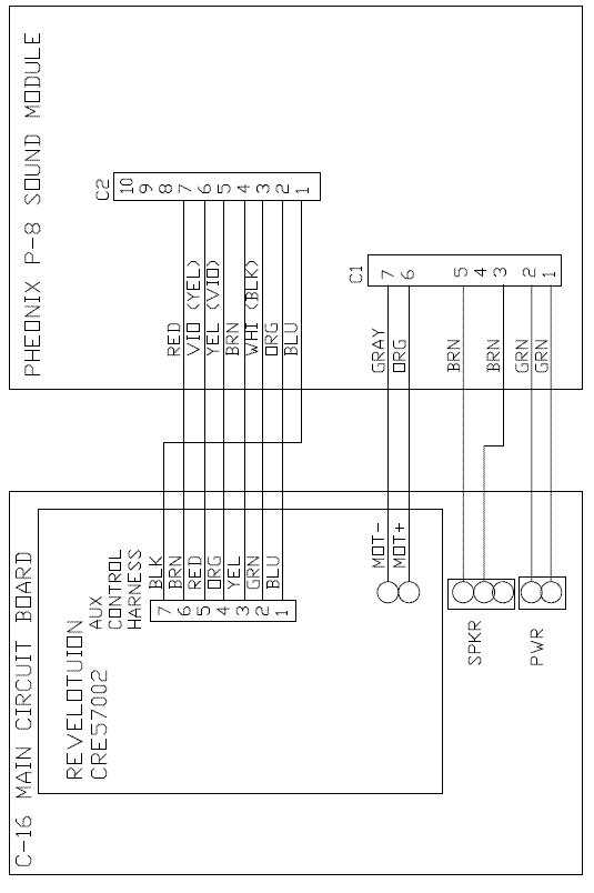
Aristo-Craft G C-16 When everything arrives, you will have a somewhat intimidating collection of "stuff." It doesn't help that there are some errors in the documentation for the locomotive and the sound decoder. Don't worry. If you do an incremental installation as I always advise, things will go well. This will break the work into smaller steps and you will know that you are doing the right things as you go along. These installation notes will probably apply to most current production Aristo-Craft locomotives, but I can't gaurantee it. I advise that you read all your manuals. There is no point in me reproducing the manuals by including every detail included in them. My primary goal here is to provide additonal detail and clarification not included in the manuals. Note that this is NOT a DCC project! This locomotive, when done, can be run on your track even if DCC powered. But this is in no way a DCC project and cannot be controlled by your DCC system. This is for people who either don't want to go with track-powered DCC or who want at least one locomotive they can run without having to clean track all the time. I fit into the latter group. When I first was interested in G scale, I looked into battery powered trains. At that time, battery powered trains couldn't pull more than a few cars, could only run for about 45 minutes, the decoders and wireless throttles didn't work well, and the sound systems sounded terrible. All that has changed. I can pull a half-dozen cars easily, maybe more, the throttle and the decoder work great, and the sound systems are fantastic. I have no intention of converting my entire fleet of locomotives to wireless, but when I just want to show off one train or I am doing track maintenance and just want to do a quick check, I now have a way of doing that with the C-16. What to Order I bought my equipment from St. Aubin Station. This whole package will run you about $1100. 1. Aristo-Craft C-16 steam locomotive By the way, you will end up with extra speakers. The loco comes with a built-in speaker. The sound system comes with a speaker and so does the battery card. I just used the speaker already installed in the tender. My Choices You have a lot of options. This installation is based on my choices. You may want to do something different. I don't do smoke. Most smoke generators can't be run dry. Also, if you have any smoke fluid in the loco, it may leak all over your loco if you turn it over. So in general, I can't be bothered with it. So I do not provide any guidance on hooking up smoke in the C-16. I wanted to minimize the wires I would have to add between the loco and the tender as well as the tender and the battery car. This in part leads to my choice of putting the sound system and the Revolution decoder in my tender. This is also a reason I don't have chuff sync with my drive wheels. Chuff sync is interesting. When I first got into sound, I wanted the chuff sync to match the wheels. However, only if you run the loco very slowly can you tell if the chuff is indeed in sync with the drivers. So who is watching? Then I obtained a LGB locomotive that had chuff sync, but only half as many as it should. Then I noticed that this produced a chuff, chuff, chuff that was pleasing when the train was running a little faster. My G-scale layout is more for show, so I adopted LGB's half-rate chuffing. Aristo-Craft does not provide any chuff sync contacts on their drivers. If they had, I would have used them. Adding them is difficult because reed relays are delicate and you have to take your locomotive apart. You will also have to run more wires betwen the locomotive and tender. To get my chuffing, I use "speed sensitive" chuffing. This is a feature of the Pheonix P-8 sound module. Either order the P-8 programmer or get St. Aubin to program your Revolution decoder BEFORE they ship it to you. No one has ever complained about the way my locomotives chuff. There is a bonus to you if you use speed sensitive chuff. The input on the P-8 sound module that would otherwise be used for chuff sync, can now be used as an additonal sound function input from your throttle. That's one more noise you can control! Get your sound module programmed for this before being shipped to you or buy the P-8 programmer. To minimize your overall investment, you can mount your Revolution decoder on the battery card. Then you can wirelessly control a number of your locomotives with only one decoder. However, if you want the Revolution to control your headlights and stuff, you will need to run more wires to your tender. I'm not worried about running many locomotives from my investment in one decoder and as I said earlier, I wanted a minimum of wires between the tender and battery car. So my Revolution decoder is in the tender along with the sound system. You can mount your battery card in most any car. The battery card has an LED on it. So I mounted my battery card into a cattle car so that I could see the LED when it was charging. The LED is not lit while the battery car is in use, so there is no unprototypical green glow coming from the car. Getting Started Under the tender, there are four switches. Turn the smoke off. Turn the lights on. Turn the motor on. Select battery for the track/battery switch. Battery Card Install the battery in the car of your choice. First make sure your battery card is working. Hook up the charger and using the on-board switch, select charge. Make sure the LED operates on the card. If you will be charging your battery through a jack external to the car, install the jack that came with your battery and make sure it is working. The C-10 battery card has an option to use a remote switch mounted on the bottom of your car. If you will be doing this rather than using a removable load like a gondola, mount your switch on the bottom of the car and hook it up to the C-10. There are two jumpers on the C-10 that have to be moved to use this remote switch. Be careful. Your battery may have a charge on it and you may get sparks if you use needle-nose pliers to remove the jumpers. The C-10 manual doesn't mention this, so I don't know if this is hazzardous to the battery or not. Sparks can always be hazzardous to your eyes, so I recommend wearing safety glasses. I thought the instructions could be clearer about the positon of the jumpers. When the jumpers are on the middle terminals and the terminals closest to the battery, the on-board toggle switch controls run/off/charge. When the jumpers are on the middle terminals and the terminals closest to the end of the card, the remote switch controls run/off/charge. The C-10 is very flexible and contains many terminals labeled + and -. Pick two (I used J4) and connect your power jack for your locomotive. Polarity is not important. Hook up to your locomotive with the run switch in off. Flip the switch to run and your locomotive should take off like a rocket. Turn it off. You are done with the battery card installation. Please note, as you complete each step below, turn off your battery card. Do not do wiring with power applied. You could damage something. Revolution Decoder Installation There isn't much to this. Remove the dummy plug and install the decoder. Be sure to read and follow all instructions in the C-16 manual and the Revolution manual (which you must print out from a CD-ROM). Hook up the remote link switch. Put the battery card in run and then get the decoder to link up with the throttle. You should be able to get your locomotive to run under control of the throttle. Turn off your battery card when done. By the way, on page 10 of the C-16 manual, it says "See the diagram on page 10 for the location of these pins." Sorry, it doesn't appear that, that diagram exists! Sound Module Installation By now, you should be getting the impression that this installation isn't as bad as all the stuff you received might imply. First, hook up the power and speaker wires from the sound module to the C-16 circuit board. Put your battery card in run and your sound card should come to life. Turn off the battery card. Second, carefully attach the orange and gray wire from the sound module to the MOT+ and MOT- terminals of the Revolution decoder. Be very careful when you do this. Too much heat could damage something. I wanted to hook into the wires between the tender and locomotive, but I couldn't figure out for sure which wires were the motor wires. My many calls and emails to Aristo-Craft went unanswered. These MOT connectors do two things. One, it tells the sound card when the locomotive is going forward, reverse, and stopped. This controls the toots that correspond with these activities. Two, the MOT connections are used for speed sensitive chuff. Be sure the store you bought your P-8 from programmed the sound module to respond to speed sensitve chuff. If you don't, your locomotive won't chuff and you will have to purchase the programmer - about $94. All you have to do now is hook up the various inputs. See the diagram below. Note that for a few wires on the sound module, I show several colors. My P-8 manual shows one color, but the wiring harness had different colors. You will now be able to control five functions from your Train Engineer throttle. Be sure to have your sound module programmed to control the five functions you want. I located my sound module over the speaker in the tender. The speaker, having a metal housing, could short out and cause damage to your sound module. I put my sound module inside a sleeve of heat-shrink tubing. That's a good solution if you have a piece of large diameter heat-shrink. Most of you probably don't. Cover the speaker with electrical tape or better yet, a sheet of plastic between the speaker and sound module.
Electrical diagram showing sound module, wireless decoder, and tender circuit card wiring. Closing Up the Tender There is a small slot in the back of the tender for the power wires to go through. Trying to stuff everything into the tender, I found it hard to line up the wires with this slot. I scraped the insulation off one of my wires. I repaired the wire and then enlarged the hole. I could do this because the wood burning C-16 I purchased had a tank - an air tank I believe - mounted directly behind the tender and hid the much larger slot I had created. Enjoy your new locomotive!
|
Copyright by Allan Gartner 1996 - 2012 © All rights reserved. You may print this for your own, personal, non-commercial use. Non-commercial, non-personal reproduction may be requested by visiting www.WiringForDCC.com/writeme.htm . All users, commercial and non-commercial, may link only to this site at www.WiringForDCC.com. Thanks to all who contribute to this site and the Q&A forum! |