|
||||
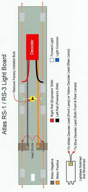
Atlas RS-1 or RS-3 by John V. Baum J V Baum@aol.com These instructions address the installation of a Digitrax DN140 decoder in either an Atlas RS-1 or RS-3. The Digitrax DH150A has been specifically designed for use in these locomotives. The decoder electronics for the DH150A are contained on a printed circuit board which replaces, and which is approximately the same size as, the plastic plastic wiring board found within these locomotives as delivered from the factory. Use of the DH150A simplifies the wiring process and, more importantly, the problem of trying to find space within the body shell to place a standard decoder. If you don't have a DH150A, don't want one, or are otherwise bound and determined to use the DN140 or other decoder of like kind, read on. 1. Remove the grab irons and shell from the locomotive. 2. Do not, in the case of the RS-3, discard the factory installed weights. Do not discard the light bars. Your may wish to use them for forward and reverse lighting as described below. 3. Unclip the front (cab end) truck leads from the annealed copper wires on the wiring board. Gently free the copper wires from beneath the plastic retainers on the front half of the wiring board. 4. Remove the headlamp from the center of the wiring board, reposition the copper wires beneath the plastic retainers, and reattach the truck leads to the ends of the copper wires. 5. At this point, you must determine where to position the decoder. On the RS-1, the decoder may be attached to the top of either truck with double sided foam tape. On the RS-3, the factory supplied weights preclude such an installation and the decoder must be attached to the surface of the wiring board. (You may be tempted to discard the weights on the RS-3 to allow installation of the decoder over the front or rear truck. Don't do it. The weights are critical to locomotive performance and proper electrical contact between rails and wheels.) 6. Clearance between the top of the wiring board and the locomotive shell is at a minimum. Clip, cut or file away any "nubs" from the surface of the wiring board at the location where you have decided to position the decoder, and attach the decoder to that location with insulated electrical tape. Foam tape is too thick for this purpose, and will elevate the top surface of the decoder to a height which will prevent re-attachment of the locomotive shell. 7. The light bars must be removed and shortened to a length which will permit the shell to be re-installed without those light bars making contact with the decoder. The shortened light bars may be notched as shown in the attached diagram, and front and rear bulbs positioned and secured within the notches. Carefully notch the shortened end to a width which will permit that notch to surround the light bulb. Notching will permit the light bar to absorb and transmit light to the lenses on the non-shortened end. As an alternative, individual lamps may be positioned in the lamp housings on the front and rear of the locomotive shell.
8. Solder the gray and orange leads from the decoder to the motor brushes as indicated after shortening those leads to the desired length. 9. Solder the red and black leads from the decoder to the annealed copper wires as shown on the attached diagram. 10. Solder one lead from the headlamp to the white decoder lead, and one lead from the tail lamp to the yellow decoder lead. The remaining leads from the two lamps should both be soldered to the blue decoder lead. Use heat shrink tubing to insulate all such connections. Secure the shortened light bars to the roof of the shell with scotch tape. I use an adhesive putty to secure lamps to the notched light bars and elsewhere to facilitate their later removal or replacement. 11. Resistors for one or more light bulbs may be installed in the usual manner. Digitrax recommends 680 ohm resistors for LED's, 560 ohm resistors for 1.5 volt grain of rice bulbs, and 250 ohm resistors for 1.5 volt grain of wheat bulbs. You may need to either increase or reduce resistor values from those which are recommended. 12. Re-assemble the locomotive.
|
Copyright by Allan Gartner 1996 - 2006 © All rights reserved. You may print this for your own, personal, non-commercial use. Non-commercial, non-personal reproduction may be requested by visiting www.WiringForDCC.com/writeme.htm . All users, commercial and non-commercial, may link only to this site at www.WiringForDCC.com. Thanks to all who contribute to this site and the Q&A forum! |