|
||||
|
Using Miniature General
Strip wires EXTREMELY gently! Cut the wire longer than you need it to be if you are not confident that you can strip the wire without cutting it off on the first try. Practice on the end of the wire before you cut it short. You may have noticed that wire insulation sometimes stretches — sometimes quite a bit! When it finally cuts, you have two strands left. Bummer, isn't it? So practicing isn't such a corny idea even if you have been stripping wires for years. For flickering firebox, mars lights, and other similar variable brightness effects, temporarily hook up resistors and lamps being extremely careful that nothing touches or shorts out. Do this until you are sure you are satisfied with the brightness.
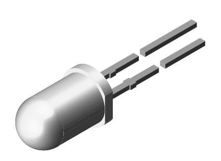
LED Basics LEDs have several advantages. They last much longer than bulbs. This means you won't be opening up your locomotive to replace a bulb and risk damaging it - screw holes stripping out, plastic snaps break, finger prints on the model and knocking off details. LEDs operate cooler than bulbs; even grain of rice bulbs. This will avoid the melting of your plastic models. LEDs typically have stiff leads. Mark Gurries recommends cutting the solid leads very short and solder on a wire very quickly. If you feel your soldering skills are not up to the job, ask someone with more skill to do it for you. While you are at it, get them to do several for you. Then you will have some the next time you need one. Don Vollrath's approach is to hold the LED in a tiny vise to keep it from moving. Then solder a small, flexible wire to it. Cut off the original lead. Don't forget to note the polarity before you cut the leads. If you hook up a LED backwards, it won't work. LEDs must be used with a series current limiting resistor. If you don't, it will burn out in a instant. See Marcus Ammann's discussion below on picking a suitable current limiting resistor. You can cover the bare connections of an LED with slip-on tubing. Which end of an LED is which? Below I will show you a typical LED along with its identifying marks and the schematic diagram. You can use this if you are installing your own LEDs. But if you are retrofitting with DCC a model that already has LEDs installed and you can't see any markings or the length of its leads have been cut, just put a 2.2k resistor in series with it and hook it up to your decoder and try it. If it doesn't light, just swap the wires to the LED. If you are really suspicous of the LED or your own ability to wire things up, use a 9V battery with a seriese resistor to test the LED rather than the output of your decoder.
Rendering of a typical LED.
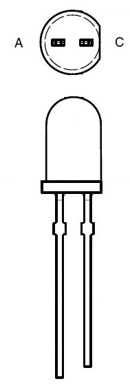
Drawing of a typical LED.
Schematic diagram of an LED. The anode (positive) side will go to the blue wire of a decoder. The cathode (negative) side will go to the function output leads of your decoder. Don't forget the series current limiting resistor! The resistor can go in series with either lead of the LED. Are bulbs good for anything? Bulbs are better suited to flicker firebox effects because their light goes in all directions. LEDs tend to shine at a limited angle. Even diffuse LEDs are at most seen at a 180 degree angle. For the same reason, bulbs are better suited at illuminating coaches. With the right shape of the LED and clear plastic parts made by model manfacturers, these points may be minor and eventually I think bulbs will be nearly impossible to get as LEDs continue to grow in general popularity. As such, many DCC devices can longer drive bulbs. |
| Color | Significant Digit | Number of Zeros |
| Black | 0 | 0 none |
| Brown | 1 | 1 0 |
| Red | 2 | 2 00 |
| Orange | 3 | 3 000 |
| Yellow | 4 | 4 0,000 |
| Green | 5 | 5 00,000 |
| Blue | 6 | 6 000,000 |
| Violet | 7 | 7 0,000,000 |
| Gray | 8 | 8 00,000,000 |
| White | 9 | 9 000,000,000 |
Here's an example:
A 4.7k (4700) ohm resistor is: Yellow (4) Violet (7) Red (2 zero's)
![]()
Measuring Decoder Function Output Voltage
If you are using a 1.5V lamp or a LED, you will need a series dropping
resistor. Here are the equations for computing the values for that resistor and how you can determine the voltage coming out of your decoder.
Contributed by Marcus Ammann
Knowing the voltage applied to an Incandescent Lamp is critical for the lamp's brilliance. A small variation in voltage with a 1.5 Volt lamp can lead to a large variation in the Incandescent lamp's brilliance.
Conventional Multimeters cannot accurately measure DCC voltages and the decoder's internal electronics (Diodes etc) further drop the voltage, so using the DCC track voltage when determining the "voltage dropping" resistor value, is not suitable.
The voltage inside the decoder that's applied to the Lamps etc, is DC.
DCC Track Voltages can vary between 11.0 Volts to more than 22.0 Volts DCC, depending on the system used and the use of scale switch.
To achieve a long lasting incandescent lamp installation, you need to
operate the lamp at its specifications. A higher voltage may provide
a much brighter effect but may cause the lamp to burn out prematurely.
A lower voltage and the lamp may be too dim or not even illuminate.
For Incandescent Lamps, a small variation in voltage can lead to a large
variation in brilliance. To get the best light effect and longevity,
a calculation is necessary where the appropriate Voltages and Current
need to known or have to be measured.
The decoder's function voltage that's applied to the Lamp, etc is DC
and in most decoders it is NOT regulated, making it approximately 0.7
to 1.5 Volts less than the DCC voltage due to “rectification”
process inside the decoder.
If you were to connect a 12.0 Volt lamp to a system that has 22.0 Volts DCC at the track, then the lamp would be burnt out instantly. Many DCC systems output between 12.0 and 15.0 Volts DCC, so it is important to know the Track Voltage of YOUR DCC system.
With the decoder's Function voltage being DC, it can be accurately measured with a “conventional mulitmeter. The function voltage will take into consideration the inability of a “conventional” Multimeter to accurately measure DCC voltages and the voltage drop due to the decoder’s internal electronics (rectifier Diodes etc). This is done by:
You can accurately measure this "Lamp" voltage, using your Multimeter by:
On your Multimeter, select "DC Volts".
Connect the Multimeter's "Plus" lead to the Function Common solder pad, blue wire or pin 7.
Connect the Multimeter's "Minus" lead to one of the Function Outputs solder pad, white wire, pin 6 or yellow wire, pin 2.
AND select the appropriate Function (Headlight etc), ON.
For 1.5 Volt Incandescent Lamps, the Function voltage
has to be reduced to the match ”the operating voltage of the Lamp,
normally achieved by wiring a resistor in series with one of the leads
to the Lamp.
For 12.0 to 14.0 Volt Incandescent lamps, they can be connected directly to the Function voltage, if the Function voltage is 12.0 to 14.0 Volts, as above, otherwise they also will need a resistor, to drop the voltage.
LEDs require a resistor to limit the current, nominally 20 mAs. See below for more details.
Calculating the “Voltage Dropping” Resistor for Incandescent Lamps.
Using Ohms Law, Resistance = Voltage/Current, the appropriate resistor’s value equals:
Function Voltage (above), MINUS Lamp’s operating voltage (1.5 or 12.0), divided by the Lamp’s Current Rating.
Example 13.36 – 1.5/.015 = 790.7 Ohms. Closest preferred value (1%) 750 or 820 Ohms.
If you DON’T know the “current rating” of the lamp:
Select DC mAs or DC Amps on your Multimeter.
Connect one lead of the lamp to your Multimeter’s MINUS lead.
Connect the Multimeter’s PLUS lead to the positive of a 1.5 Volt battery.
Connect the other lamp lead to the negative of the 1.5 Volt battery.
The Multimeter will display the “current rating” of the lamp eg 15 mAs (.015A), 20 mAs (.02A) etc.
The wattage of the resistor will depend on the current rating. For the below currents of:
15 mAs = ¼ Watt
30 mAs = ½ Watt
40 mAs = 1 Watt
60 mAs = 2 Watt
Calculating the “Current Limiting” Resistor for LEDs
These days (2013), LEDs are much brighter than previous LEDs. We can operate LEDs at much lower than their “nominal” current of 20 mAs, so there is no need for a “calculation” like those that are necessary when using Incandescent lamps. A variation in track voltage will show no appreciable change in brilliance.
The general recommendation of the “Current Limiting” resistor was a 1,000 Ohm ¼ Watt resistor.
If your particular LED “effect” is too bright, increase the value of the resistor. Many are using 1.5 to 2.2 K (1,500 to 2,200) Ohms. I have used 10 K (10,000) Ohms for a Steam loco Headlight.
For more details, see:
http://www.members.optusnet.com.au/nswmn1/Lights_in_DCC.htm
![]()
![]()
Equation for Dropping Resistors
These equations have a lot of uses. It is not the purpose here
to describe all those uses. The intent is to provide the equations for those
that know
how to use them. I do provide two common and useful examples below.
| Where: VPS VL VD IL R W |
is voltage provided by power source. is the voltage rating of the lamp or LED. is the forward voltage drop of a diode if used. is the nominal current in amps for lamp. value found for resistor in ohms. wattage value found for resistor |
The term VD is 0.7V if you are using a series protection diode.
Otherwise it is 0V.
The term IL is the nominal operating current in amps. If 20mA, then use 0.02.
If 100mA, then use 0.1.
The term VL is the nominal operating voltage of the bulb or LED. The nominal
operating voltage for an LED is typically 2.6V. Blue LEDs are typically 3.7V.
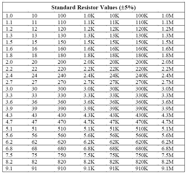
You will find that resistors are not typically available in every possible value. Therefore, use the commercially available value that is close to or higher than the value you calculated.
In determining the wattage of the resistor, use the value for R that you decided to buy. Once you determine the wattage, use a resistor with a wattage rating that is higher than the value you calculated.
See the two circuits below for examples.
![]()
![]()
A Primer on LED Strip Lights
by Keith Elrod
President of the Tennessee Chapter of the "I Listen to Allan" Club!
LEDs (Light-emitting diodes) strip lights are very popular in model railroading. With my background in Entertainment Lighting I often get questions on lighting for our hobby, including these strip lights. I have a lot of them on my layout (Tellico Southern Railroad), along with Woodland Scenics’s Just Plug system and Menard’s Pre-lit structures. I really love the Just plug system, but we’ll make that a separate article.
The strip lights typically are provided in rolls of approximately 16.4' (5 meters) with an adhesive backing. The most common configurations are 12V and 24 watts, which is 1.5W per foot. Most of these SMD (Surface Mount Diodes) can be cut after every three diodes. The cut line is clearly marked with 4 copper dots, which are the soldering (connecting) points. Some are spaced at every 6 units. This makes them ideal for placing inside structures; just cut to the size you need. The soldering points are very close to each other, so a technique I use is to apply Liquid Electrical Tape over the soldered points, after testing the connection. You can apply a second coat, if needed, but allow 24 hours for full curing. Note that there are 24V strips, so make sure you choose the correct voltage for what size bus you will use.
Color output is an important factor so pay attention to this in purchasing the desired color you want. My preference is for Daylight, but warmer versions (more yellow) are available. Some manufacturers only list those designations, but two better indicators of the light output are the kelvin number (measured in degrees) and the lumens rating. The kelvin # indicates the quality of the light. A low number around 2700k means it is a warm (yellow) light, while a high number in the 5000k to 6500k indicates a bright, white daylight. Most LEDs that you buy for your home will usually have at least one of these indicators. I have the 5000k & 6500k LEDs in my overhead train room lighting. The official definition of a lumen is long and boring. In short, lumens equal brightness, and watts do not. Watts are bad, of course, but they measure energy use, not light output. With all the new, energy-efficient LED technology, we can no longer rely upon wattage to indicate how bright a bulb is.
A variety of colors are available, including red, green, blue and yellow. I use blue strips behind a lot of structures to add additional, but subtle, lighting highlights. [Note that my layout is being built for nighttime operations.] RGB, RGBW (Red, Green, Blue & White) and RGBAW (Red, Green, Blue, Amber & White) combination units are available. The RGB strips will usually come with a remote where you can program various effects. I have a set of these installed in some caverns programmed to do slow fades between a variety of colors. The RGBW and the RGBAW units are typically used in high-end operations such as automated theatrical lighting and can be very expensive. Another option is choosing waterproof or non-waterproof versions. For our hobby's purposes, we do not need the waterproof versions, which will typically be higher-priced.
Size, light output and power consumption are very important as there are a variety of options. Pay attention to the 4-digit numbers listed after the SMD designation. These numbers define the size of the LED chip. One of the first, and most common sizes is the 3528, which means it is 3.5mm x 2.8mm. I have used a lot of these. There is also a newer version, the 2835, which is the same size but oriented differently. Manufacturers have been able to increase the light output of these while reducing the power consumption. Typically there are 300 units per roll. The 5050's provide a larger light output compared to the 3528's, but usually have 150 units per roll. Pay attention to the power output on these as they range from 36w to 72w per roll. Adjust your power supply as needed. Note that some rolls come with a power supply, while most do not.
Narrow strip lights are also available for projects that have limited space, such as a roof overhang. They tend to be super bright producing higher kelvin, lumen & wattage numbers and are more expensive. A LED dimmer may be required to bring down the light levels to match other strips you might have. The regular size strips are approximately 3/8" wide (9.25mm) while these narrow strips are available in several widths that are narrower than this. So pay attention to the numbers before ordering these.
LED strips are polarity dependent, but are clearly marked at each cut mark with "+" and "-" marks. You can solder wires at these connections or you can use a variety of connectors made specifically for this purpose. I have a large roll of telephone wire which the previous owner of my house left me. I strip the outer insulation off and have several sets of color-coded pairs of 24 AWG wire which have worked out great for me. I've also installed a 12V buss around my layout. Along that buss I have installed some bus bars. Wherever I install a structure with a LED strip light I just run the wire down through the layout to one of these bars.
Can you dim these strip lights? Yes you can and I use a readily-available LED dimmer. I have one installed at the beginning point of my 12V bus, so that I can control everything on the buss with just one dimmer. LED dimmers are available from Micro-Mark and other online sources. The one I use is rated at 12-24V and 8 amps.
These light strips provide a great solution to many lighting needs in our hobby. They are safe to use, cuttable and linkable, easy to install and provide flexible operations. They are readily available in Home Improvement stores and online, such as Amazon, where you will find a variety of choices. Happy modeling.
LED Strip Light Supplies |
Closeup of cut line (bottom) |
Keith Elrod
Knoxville Area Model Railroaders Inc, NMRA member
Broadway Master Electrician & LD (Lighting Designer)
![]()
![]()
Using a grain-of-rice light bulb in a locomotive.
You will need a voltage-dropping resistor in series with grain-of-rice bulb.
Use the equation above. For HO:
To compute resistor value on your own, see above Equation for Dropping Resistor.
VPS = 13V
VL = 1.5V
VD = 0 (since you have no diode)
IL = 15mA = 0.015A
R = 767 ohms. You can use XXX ohms from Radio Shack.
Using a 100 and 680 from Radio Shack in series, W computes to be 0.165.
Use a ¼W resistor or larger. Radio Shack has a better selection
of ½W resistors.
![]()
![]()
Using an LED to Indicate DCC Track Power On
You will need a voltage-dropping resistor in series with the LED. You will also need a reverse polarity protection diode.
To compute resistor value on your own, see above Equation for Dropping Resistor.
VPS = 14.4V
VL = 2.6V
VD = 0.7V
IL = 20mA = 0.02A
R = 555 ohms. You can use 560 ohms from Radio Shack.
Using a 560 from Radio Shack, W computes to be 0.224. Use a 1/4W resistor
or larger. Radio Shack has 560 available in ½W size. Use that.
![]()
![]()
Here are some resistor values already computed for you:
Resistor Needed When Using a 1.5V Grain of Rice Bulb on the output of a decoder. Standard resistor values shown in parentheses. I would use the first standard value in parentheses. If you want to get closer, I have shown the summation of standard values after the comma. All these resistors can be 1/4 watt.
. |
. |
15mA |
13mA |
11mA |
10.5V |
N |
600 ( 620) |
808 ( 820) |
955 (910, 910+47) |
12.9V |
HO |
768 (750, 750+18) |
992 (1k) |
1,173 (1.2k) |
17.6V |
G |
1073 (1.1k) |
1354 (1.3k+51) |
1.6k (1.6k) |
Here are some resistor values using LEDs either on the output of a signalling circuit or a decoder. Standard resistor values shown in parentheses. You can probably use the first standard value in parentheses. Values were based on you using an LED with a 2.6 voltage drop. All these resistors can be 1/4 watt.
| . | . | 20mA | 15mA | 10mA | 5mA | 3mA |
| 5V | . | 120 |
160 |
240 (240) |
470 (470) |
800 (820) |
| 10.5V | N | 395 (390) |
527 |
790 (820, 750+39) |
1580 (1.6k) |
2633 (2.7k, 2.4k+240) |
| 12.9V | HO | 515 (510) |
687 (680) |
1030 (1k, 1k+33) |
2060 (2k, 2k+62) |
3433 (3.3k, 3.3k+130) |
| 17.6V | G | 750 (750) use 1/2W |
1k |
1.5 (1.5k) |
3k (3k) |
5k (5.1k, 4.7k+300) |
![]()
![]()
FLICKERING
FIREBOX |
As a steam photographer, I always considered it a bonus if I happened to get a bit of flame in the picture. The flicker adds drama to these living machines. Now that our models can have this dynamic element too, we have another reason why modelling steam is better than diesel! Okay, so model steam locomotives are often finicky. They are just being prototypical!
I don't mean to be a killjoy, but it has been pointed out to me that only oil-fired locomotives have a flickering firebox. Coal and wood-fired locomotives have a nearly constant glow. But flickering fireboxes sure look good! So go ahead and use one anyway - it's your railroad. If a rivot counter critiques your flickering firebox, you cna turn the function off.
Just so you my perspective and take them into account while reading my comments, here's my personal preferences for firebox flicker.
I figure you should easily see it when looking beneath the cab floor at night. Perhaps you see it reflecting off some of the parts underneath the locomotive. Also visible through the small holes in the firebox doors. During the day, it should be visible when looking directly under the cab floor only.
On a full size locomotive, the cab floor is at or higher than the eye level of most people. On model trains, is more like waist level. The viewing angle, if modeled exactly, would be rather shallow.
So I use my bulbs with the lowest value resistor to make the flicker visible without too much effort.
Firebox brightness and appearance are largely a matter of taste. So the resistor values specified are the minimum you should use. You might want to purchase the next two or three higher standard values, which I will list. You can try them if you prefer a dimmer flicker. Temporarily make your being extremely careful that nothing touches or shorts out and smokes your new toy. Do this until you are sure you are satisfied with the brightness.
Also, if you use a bulb different than the one I used, it may act differently even if its voltage and current ratings are the same as mine.
![]()
![]()
Flickering Firebox — 1 Lamp, 1 Circuit:

Your typical flickering firebox circuit. R2 should be about 22 ohms for HO installations and most grain of wheat bulbs. Other values you may want to try if too bright are 27 ohms, 33 ohms, or 39 ohms.
Radio Shack's 12V precolored GOW bulbs don't seem to work too well for flickering firebox - at least not with decoders that don't provide a low keep alive voltage. The filaments hardly get warm in this situation. The bulbs light fine with steady voltage applied.
![]()
![]()
Flickering Firebox — 2 lamps, 2 Circuits:
Zana of Digitrax suggested that I might like the effect of two flickering firebox function outputs. How could I resist anything that would make the fire dance around instead of simply pulsating randomly would be a plus?
Radio Shack's 12V precolored GOW bulbs don't seem to work too well for flickering firebox — at least not with decoders that don't provide a low keep alive voltage. The filaments hardly get warm in this situation. The bulbs light fine with steady voltage applied.
![]()
Flickering Firebox — 3 Lamps, 2 Circuits:
You can use the 6V Radio Shack precolored bulbs with a large dropping resistor. But why throw away 6V when it could be lighting another 6V lamp? A pack of bulbs, which includes a red, yellow, and green lamp, cost about the same as one GOW bulb. The lamps are Radio Shack P/N 272-1098 rated for 60mA. R1 should be 22 ohms or larger for HO installations. Other values you may want to try if too bright are 27 ohms, 33 ohms, or 39 ohms.
The single lamp could be a grain of rice bulb and used for the synchronized flickering firebox. This feature is available in Soundtraxx modules. It brightens when the sound of coal being shoveled into the firebox sound is being generated and the firebox doors would be open. Grain of rice bulbs are about 1.5 volt at about 15mA. R2 should be 730 ohms for HO installations. You can't buy a 730, but you can buy a 750. Any combination that totals 700 or so will probably work fine for you.
![]()
![]()
Flickering Firebox — 2 Lamps, 1 Circuit:
You can use the 6V Radio Shack precolored bulbs with a large dropping resistor. But why throw away 6V when it could be lighting another 6V lamp? A pack of bulbs, which includes a red, yellow, and green lamp, cost about the same as one GOW bulb. The lamps are Radio Shack P/N 272-1098 rated for 60mA. R1 should be 22 ohms or larger for HO installations. Other values you may want to try if too bright are 27 ohms, 33 ohms, or 39 ohms.
![]()
Flickering Firebox — 4 Lamps, 2 Circuits:

Why not indulge in a little overkill? So I created the four bulb circuit. It gets a little crowded, but it sure looks good! This circuit probably isn't appropriate for those wishing to use synchronized flickering firebox. The lamps are Radio Shack P/N 272-1098 rated for 60mA. R1 should be 22 ohms or larger for HO installations. Other values you may want to try if too bright are 27 ohms, 33 ohms, or 39 ohms.
![]()
![]()
Mars Light
When using an HO locomotive and a grain of wheat bulb, DCC manufacturers leave it up to you as to the value of R2. I recommend you use the lowest value they suggest. For Digitrax, that is 22 ohms. This makes the Mars light as bright as possible. Using the default decoder values for mars light brightness, I think you will agree, if anything at all, it's not bright enough! For Digitrax, see their manual on CV 62. You will be able to make the mars light brighter.
![]()
![]()
Diesel Strobe
Don Vollrath makes diesel strobes by using yellow Christmas LEDs that have a molded in reflector for horizontal light dispersion. Paint the end black and poke it through a hole in a diesel cab.
![]()
![]()
RECOMMENDATION 12-3: Lighting Passenger Cars
Considerations of Using Lighted Passenger Cars:
Be sure if you are using lighted passenger cars, that reversing sections are longer than the longest train you will be running. You have probably heard that if a train is entering a reversing section at the same time as one is leaving, this will cause a short and shut the booster down. A lighted passenger car will do the same thing. So make sure your reversing sections are long enough.
How many passenger cars can be run on DCC?
If you only have a dozen or less passenger cars, you probably don't need to worry much about the load the passenger cars will be putting on the booster(s). However, should you be so fortunate to have many more than that, the math is simple.
Booster current (usually 3.5 or 5 A) - the load of the locomotives (usually approx 3/4 A) - (# of lit cars x their current draw (maybe .2A))
My estimates above should be a bit on the high side.
Definitely buy the 5A boosters. You can even buy the 8A boosters, but I don't recommend them for HO or smaller unless you really need to. Instead, break the layout into smaller sections that can be handled by a 5A booster. Note: Idle locomotives only may draw .2A or less. Idle, lights off, and no sound, definitely less.
Do you want every car lit?
Or only those part of an active train, or soon to be active. If you want them off, you may want to go as far as putting a decoder into each car. That's convenient, if not inexpensive. You could hook them the cars to save money on decoders, but I find that wires between cars are a fair amount of trouble. If you can afford decoders, I'd go that way.
Or you could park them on tracks in a yard or whatever and use a toggle switch to kill the power to that track.
You should figure out how much current your cars will draw. I haven't done a lighted passenger car yet, but I suspect the average modeler would want it dimmer than the average toy passenger cars that I had when I was a kid. So light a car any way you want that gives you the desired effect and measure how much power it draws at about 14V.
What if I don't want to use a decoder?
You, for the most part, can simply run a lighted passenger car directly from the DCC track! In HO and smaller, it's that simple!
Those running O or G, may want to use 19V LGB light bulbs; if you can find them. Or you can use 14V bulbs and put resistors in series with them. To figure the resistor value = (19V[track voltage]-14V[bulb voltage])/0.06A[bulb amperage] = 83 ohms. Use any standard value from 82 ohms to 100 ohms should work fine. The wattage rating of the resistor needs to be 1/2 watt.
If you want to use 12V or lower voltage bulbs and want something that will keep the lights from flickering when you hit a dirty spot, use the 12V power supply circuit described below.
![]()
![]()
RECOMMENDATION 12-4: 12V Power Supply Circuit — Millions of Uses!
Do you need a circuit that will power sound systems, light cars, anything you can think of, from DCC or 12VAC? Here it is, in this example, it is used to power a sound system. It consists of Z1, C3, C4, C5, and usually a 7812 voltage regulator. The red and black wires have the 12VDC on them. This circuit can produce up to one amp.
C4 and C5 are 0.01uF capacitors rated at typically 50V — they are common. Z1 is rated at 1A and 50V — also common. C3 is usually rated at 25V and for starters, is a 1000uF capacitor.
There are a lot of variations on this circuit.
This is very compact and can fit in a Z-scale car if you are determined enough. There are many ways to make it smaller. Many of your uses don't draw anywhere near one amp. Therefore, you can forget putting a heatsink on the voltage regulator. Another way to make the circuit smaller is use components that are rated closer to the voltage you will be applying to the circuit. For example, C4 and C5 can be gotten in 25V and sometimes lower voltage ratings. C3 can definitely be gotten in 16V ratings. Don't worry about Z1. Its size isn't affected by applied voltage.
There are few cautions I must give you.
1. If you are running this from a 12V transformer: You probably aren't concerned about size. So use 25V or higher components. Without getting into the technical details, a 12V transformer, usually puts out, as far as these components are concerned, almost 18V. Note: With DCC, this isn't an issue.

2. If the voltage rating of C3 is below the applied voltage IT WILL EXPLODE: Got your attention, did I? There is a safety margin built into these devices. But if you apply too much voltage to C3, an electrolytic capacitor, IT WILL EXPLODE WITH INJURY, ESPECIALLY TO YOUR EYES, POSSIBLE.

3. If you hook up C3 backwards, IT WILL EXPLODE regardless of whether you applied too much voltage or not.
So whatever you do, don't undersize C3. It's okay to have it just big enough, but don't make it too small. Also consider whether you will be taking your car with this circuit in it to another layout running a higher voltage.
Another size choice you can make is using a lower value of capacitance for C3. If you are running the circuit off of 12VAC and you want an amp, use the 1000uF capacitor. But at DCC frequencies, a smaller capacitor can still produce an amp. If you are putting this inside a car, you probably don't need anywhere close to an amp. So you can probably use a 100uF or a 47uF or maybe even a 22uF or a 10uF and get the results you want.
On the other hand, the larger the value of C3, the more immune the circuit will be to dirty track. In that case, you may want to stick with the 1000uF or go up to 2200uF, 3300uF or larger. Larger values, especially when you are drawing much less than an amp, may allow something, like lights or a sound system, to stay on for a few seconds upon loosing DCC power. Maybe you want that.
The voltage regulator shown is a 12V one, but you can get them in other voltages as well from the same company you would buy the 12V regulator from.
![]()
![]()
SUGGESTION 12-5: How to Get 1.5VAC to Run Grain of Rice Bulbs
This has nothing to do with DCC. Call this one a bonus.
1.5V is somewhat of problem to get. Common voltage regulators don't go this low. Modelers have come up with some interesting ways to get 1.5V. Because they often had some sort of drawback, I came up with my own way of doing it. It's simple!
This idea works great and is easy to implement in countries using 120VAC out of the wall or approximately that amount. This idea can still be used in other countries, but its ease of implementation will depend on what voltage transformers are available.
ONLY
do this if you FULLY understand what I am talking about. If not, get with
an electronics friend of yours to help you out. Before putting this circuit
into operation, test it with a voltage meter connected by clips. DO NOT be
touching any of the wires with your fingers when testing it. FAILURE TO HEED
MY WARNINGS COULD BE FATAL.
What I am about to suggest is common. Its how power gets from a power plant to your house - through the use of multiple transformers. However, even if you have done electronics projects before, you may have never hooked multiple transformers together. So this may seem odd or confusing to you. If it is, DO NOT DO IT. IT COULD KILL YOU if hooked up wrong.
Here's the idea. Take two transformers, each with 120V in, and 12.6V out. Each has a voltage transformation ratio of less than 10.
1. With a fuse and a switch, wire the first one up so you can plug it in the wall. You will get 12.6VAC out.
2. Take the second transformer. Instead of connecting its wires that are labeled 120V to 120V, connect them to the 12.6VAC of the first transformer. You will get about 1.3VAC!
Note: You could have one transformer putting out 12.6VAC. You could run this 12.6VAC around your layout. You could then have a small transformer in each town to produce the 1.3VAC to light that town. Or you could just run the 1.3VAC around your layout. Which way to do it, is up to you and what you are modeling.

If you are in a 110/120V country, T1 and T2 should be 120V:12.6V transformers. In a 220/240V country, T1 should be a 220:25.2V transformer. T2 should be a 220:12.6V transformer or the nearest equivalent. The fuse, F1 should be no larger than ¼ amp.
CONSTANT LIGHTING CIRCUITS |
Power Supply Considerations
Below are a number of circuits with differing power supply circuits. Since DCC is constant voltage square wave AC, for the most part, the circuits below are interchangeable. Even the most sophisticated circuit with a 10,000 micro-farad capacitor and a LM317T regulator is not expensive. So you have choices. This section aims to help you to decide which one is right for you.
Before I dive into LEDs, note the circuits for the Tomar marker lights that use 1.5V lamps. The trick you will see with two diodes that are around each lamp can't be used with LEDs.
From an electronics standpoint, LEDs don't require fancy power circuits. As long as you don't exceed their design limits, they will work. If the lighted car stops on a dead frog, the LED will simply go out.
On the other hand, a coach that goes out when stopped on a dead frog or flickering a little bit as it rolls down the track may be something you may feel you want to avoid at any reasonable cost.
Perhaps the biggest drawback to the most sophisticated circuits is finding a place inside a coach to hide it.
So here are the considerations on the circuits below:
Circuits using the LM317T regulator will likely provide the least amount of flicker. The package that it comes in is shown below. Buy one and see if you have room for it. Note that the circuits using the LM317T can probably only supply enough voltage to power two white LEDs in series.
Circuits using large capacitors (2,200 - 10,000 microfarads). The higher the value of capacitor, the bigger it physically is. Buy one and see if you have room for it. Capacitors larger than 2,200 microfarads will need some sort of circuit to limit inrush current and tripping your booster off line. The circuits below showing the 100 ohm resistor and the 1N4148 diode limit inrush current. While all the large capacitors shown below are also shown with LM317Ts, you do not have to use them with LM317Ts. If you use large capacitors with LM317Ts, you will only be able to use with two series LEDs. If you don't use the LM317T, you will be able to use them with three series LEDs. Four will not be possible.
Finally, the simple circuit that does not use the LM317T, large capacitors, and an inrush current limiting circuit, will be the cheapest, the smallest and easiest to hide, but will be the most susceptable to flicker or going out completely. Four white LEDs in series is poss
Should you decide you would like the LM317T circuit in places with room to hide and less sophisticated circuits where you don't have room, with a little work, you can brightness match the different circuits.
Circuits contributed by Don Vollrath. Ask Don questions on the Wiring for DCC Q&A Forum.
Three circuits are designed to operate Tomar Adlake incandescent marker lights which look great on a caboose. Each one gets progressively better as you run down the page. Operating the lamps in series keeps the current draw from the track as low as possible. The diodes in parallel with the lamps in the first two examples form a shunt regulator to limit the voltage across each lamp to about 1.3V... even if one lamp burns out. This is a good brightness value and extends the operating lifetime. One can use a 220 ohm resistor for a little more regulated brightness if necessary. If operating in a really dark room one can increase the current limiting resistor value to 270 or 330 ohms for a dimmer, more realistic look.
The other two circuits use the LM317 as a current source limiter. This works best to hold the lamps at constant brightness during interruptions of power from the tracks as voltage on the energy storage capacitor decays.
If you haven't read the section above on power supply considerations, click here.
The last circuit shown is for LEDs. However, it
has a practical limit of only 1 or 2 white LEDs at constant
brightness with their nearly 3.5V operating voltage. One can
successfully operate 1-3 LEDs of other colors due to their lower
operating voltage requirements.
If more lamps are desired one can add a second regulator and
lights in parallel with the first, taking power from the same
energy storage capacitor.
In each circuit one resistor adjusts and limits the current
to control brightness. The Tomar marker lights look best when
operated at 30-40 mA. Usually 8-15 mA is bright enough for LEDs.
Using high brightness LEDs at lower current will provide the
longest power interruption time ride-through.
Parts List
I have provided a Radio Shack parts list for the above circuits. Radio Shack doesn't sell all values as specified in Don's circuits. Use the nearest value.
The value of the capacitor is not critical. Simply the more capacitance you have, the longer the lamp or LED will stay lit when you hit a dirty spot. Capacitors can also be put in parallel to get whatever value you are after. Also, you may want to use more of the smaller value capacitors to give you more flexibility and deal with whatever space restrictions you have. So you could use 10 1000uF or 2 4700uF or even a 1000uF capacitor in parallel with a 4700uF capacitor.
Part |
Description |
Radio Shack |
Diode |
1N4148 |
276-1620 |
Resistor |
22 ohm, 1/2 W |
271-1103 |
Resistor |
33 ohm, 1/2 W |
271-1104 |
Resistor |
47 ohm, 1/2 W |
271-1105 |
Resistor |
68 ohm, 1/2 W |
271-1106 |
Resistor |
100 ohm, 5%, 1/4W |
271-1311 |
Resistor |
150 ohm, 1/2 W |
271-1109 |
Resistor |
220 ohms, 1/2 W |
271-1111 |
Resistor |
270 ohms, 1/2 W |
271-1112 |
Electrolytic Capacitor |
1000uF, 35 WVDC |
272-1032 |
Electrolytic Capacitor |
2200uF, 35 WVDC |
272-1020 |
Electrolytic Capacitor |
4700uF, 35 WVDC |
272-1022 |
Bridge Rectifier |
1.4A, 100V |
276-1152 |
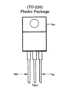
Voltage Regulator |
LM317T, 1A |
276-1778 |
![]() A
picture of the LM317T in the TO-220 package is shown here.
A
picture of the LM317T in the TO-220 package is shown here.
![]()
Constant LED Lighting for Passenger Cars and Cabooses
Polarity Issues - Read this FIRST!
All the components you will use in this section are polarity sensitive except for the resistors. Polarity sensitive means there is only one way to hook things up for them to work right.
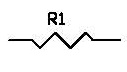
A resistor
|
Capacitor Safety If you hook up the capacitor wrong, it will explode or catch fire! This could result in burns, severe injury to your eyes or blindness, a melted model, or damage or loss of your property. Wear safety glasses or googles. If you follow the directions here carefully, capacitors are safe to use. If you see a capacitor begin to swell, duck below your table top. If you can do so rapidly, kill the power on your way to the floor. |
|
Capacitor polarity: Capacitors have two leads; a positive one and a negative one. Generally, only 1 lead is marked; positve or negative.
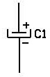
A polarized capacitor
There are two ways you can get a capacitor wrong in a power supply circuit like the one you will be building here. One, is to hook up the capacitor wrong to the rectifier circuit. Two, is to have your rectifier circuit backwards. Both situations will cause the capacitor to explode or catch fire.
Rectifier polarity: Bridge rectifiers have a positive (+) and negative (-) output.
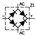
A bridge rectifier
If you don't already own a digital volt meter, invest in one now. Feel free to buy the cheapest model you can find. It will do fine. Put it on DC-Volts and select the 20V range.
Attach the red lead to what you think is the positive (+) output. If you bought a bridge rectifer, the outputs are usually marked. Hook the black lead to the negative (-) output. Hook the AC inputs of the bridge rectifier to your track. If you have everything right, you should read around 13 or so volts. Most importantly, you should see a positive number. If the digital volt meter is reading a negative -13 or so volts, you are reading your bridge rectifier wrong. Swap your meter leads to get a positive number.
Once you know which output of your bridge rectifier is positive and negative, it is now safe to proceed.
LED (Light Emitting Diode) polarity: If you hook up an LED wrong, it simply won't work. Hooked up incorrectly briefly usually won't damage the LED. If using an LED with leads, the shorter lead is the negative (-) lead. These same type of LEDs have a flat side on them, the flat side denotes the negative (-) lead. The flat side may not jump out at you. Just rotate the LED is your fingers and you will feel the flat spot go through your fingers.
A LED
You can also determine the polarity of an LED by setting your digital meter to the diode/continuity setting. If you intend to use this method, make sure your meter has such a setting. Usually, it will be denoted by a diode symbol on it's dial. Hook up the meter to an LED. If the LED lights up a little, the terminal on the LED that is attached to the red lead of your meter is the positive (+) terminal and the black lead is attached to the negative (-) terminal. If it doesn't work, try swapping the meter leads.
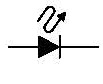
The polarity of an LED is denoted in schematics by a short line at the head of an arrow. The line denotes the negative (-) end of the LED.
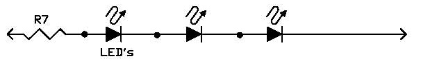
Overall Circuit - aka Start Your Project Here:
There are a large variety of configurations you can use to light your passenger cars and cabooses. All of them require the basic circuit below with the bridge rectifier and capacitor. Then you need to decide, are you lighting a passenger car (generally a coach)? Will your passenger car (generally an observation car), have markers? Will the observation car have a drum head? Or are you lighting a caboose? Will it have markers? If you answered "yes" to any of these, you will need to wire in one or more of the optional circuits. Below the basic circuit, are a variety of circuits to be used in place of one of the optional circuits referenced in the basic circuit below.
Each optional circuit you use, should have its own resistor so that you can adjust its brightness independently of the other options. For example, you may want your interior brighter than your marker lamps. So their brightness should be set independently.
Component |
Mouser |
| Z1 bridge rectifier,
1A |
621-DF04M |
C1 470uF, 25V capacitor |
667-EEU-TP1E471L |
| C1 220uF, 25V capacitor |
667-EEU-FC1E221 |
| C1 100uF, 25V |
667-EEU-TA1E101 |
If you haven't read the section above on power supply considerations, click here.
General Component Selection:
You don't have to use the specific parts I have identified. I just gave you specifics so that not knowing anything else, you can buy something that will work.
Capacitor Selection:
The purpose of the capacitor is to smooth out fluctuations due to dirty track and other discontinuities like going over points, frogs, and insulated joiners. Since DCC is a high frequency square wave and all you are driving are LEDs, one of your options is to not use any capacitor at all! If you have really good track, turnouts, and lots of good contacts on your wheels, you may not notice any flickering or not flicker as much.
You probably won't be that lucky. Sooooo......
The more capacitance you use, the more tolerant your lighting system will be to dirt and discontinuities. It is a little difficult for me to tell you just how much is the maximum you can use. I used a 2,200uF (microfarad) capacitor on a small starter DCC system. It worked fine. However, if you have a number of passenger cars, all with 2,200uF capacitors in them, your DCC system may see them all as a short. There are ways to limit the inrush current so this doesn't happen. The circuit will be more complicated. Which means it will be harder to hide your circuit in a passenger car. This will be the topic of a future addition to this website.
With the 2,200uF capacitor, the LED was bright for about 1-1.5 seconds. Then it stayed lit for many seconds with the LED configured to draw 20mA (milliAmps or thousandths of an amp.) If you don't have your lighting configured to draw this much current, then the LED may stay lit brighter longer. The good news is that 20mA may make your coach interiors too bright. You may find coach interiors will only need 5-10mA. Markers may only need a couple of milliamps.
If you use a 470uF capacitor, you can probably put one of these in each car and not adversely affect the short detection of your DCC system. You can also use a 100uF or 220uF capacitor. The lower the value, the less discontinuity protection you will have, but the lower the value of the capacitor, the smaller it is. So if you are pressed for space, you may want to use one of these lower values.
In a coach, with little room to hide things, you can also buy several 100uF or 220uF capacitors and put them in parallel. You will be able to better hide these smaller capacitors along the ceiling of the coach.
You may have noticed that the values of capacitors seem to have odd values. They do! These are standard values. You can't readily buy a 200uF or 500uF capacitor. Don't loose any sleep over this.
Electrolytic capacitors have a capacitor value in microfarads and a voltage rating. I recommend using one rated at 25V. If not building Don's circuits with the current inrush limiter, using one rated at a lower voltage is risking. If your track voltage is a little high, the capacitor could explode.
LED Selection:
This section is one I intend to expand with part numbers and parameters to help guide you in the selection of LEDs. For now, I'll just list the general considerations.
I'll start off with a downside to LEDs. Miniature lamps give off light in all directions. LEDs don't. Some have a dome and give off light up to 180 degrees. But most are not much more than about 55 degrees. Given this, this may be one reason you will want to light your coaches with pairs of LEDs - one pointed to each side or down the length of the car. The angle of the output light will be the subject of a future addition to this section of my website.
If you have ever bought a lightbulb at your local home improvement store, you may have noticed that you can buy different shades of white. If you didn't notice this at the store, then when you got home, you may have noticed that you new light bulb doesn't match your existing light bulbs. The same is true of LEDs. These different shades of white is called color temperature. (This is the same thing that your digital camera uses in setting white balance.)
If you want a LED that resembles a typical incadescent bulb, you want a "warm white". This would be appropriate for coach interiors, head lights and mars lights. If you want a beacon, you will want a whiter white like daylight white. Some white are bluish as you may have noticed on some modern automobiles. Unfortunately, many LEDs are sold without telling you what shade of white. This will be a topic of a future addition to this website as I try to help you out with this.
Another thing to notice about LEDs is that some are diffuse are some are more specular. You cannot see the LED device inside a diffuse LED. The specular ones, you can. For lighting coach interiors, drum heads, or beacons, I recommend the diffuse ones. For headlights and mars lights, you could use the specular ones.
LEDs come in different shapes and sizes. The typical through-hole ones come in 3mm and 5mm or even bigger. I think in most cases, you will want the smaller 3mm ones just because they fit inside models easier.
Some LEDs don't have leads. They are called surface mount devices. Unless you are really good at soldering, you will probably find these difficult to solder to.
Selecting Resistor Values:
For each circuit, I have created a table of suggested values for the resistors. There are other values of resistors you can use. Just be sure to at least use the lowest value I have shown in each table. Any higher value is fine.
You can either try different values or use a resistor selector box or resistor decade box. I have a good selection of resistors, so I just try different values to suit my objective. You can also build a resistor selector box.
You will notice resistors come in the same seemingly crazy values like capacitors! There is actually a good reason for this, but I won't bore you with those details.
I have listed the resistance value in ohms, and the size of resistor to use. The smallest wattage rating I have listed is a 1/4W. In many cases, a lower rating could be used. But the parts tend to be very small making them harder for you to work with them. So a 1/4W is the smallest size I suggest you use.
The Optional LED Circuits
I have a number of LED configurations below. Instead, I am identifying them by the resistor used to limit the current.
You will notice that the maximum number of LEDs I have in series in any of my circuits here is 4. This is because of the amount of voltage it takes to run each LED. So you can have 4 or less LEDs in series, but not more. If you need more LEDs, you can put more in parallel.
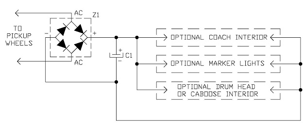
R6 Circuit
Here is a circuit that you can use to light the length of a coach or when you only need a total of four internal LEDs.
Brightness Current |
Resistor Value |
Mouser |
| 20mA |
10 ohm, 1/4W |
660-MF1/4LCT52R100J |
15mA |
13 ohm, 1/4W |
660-MF1/4DCT52R13R0F |
|
10mA |
20 ohm, 1/4W |
660-MF1/4CCT52R20R0F |
5mA |
39 ohm, 1/4W |
660-MF1/4DCT52R39R0F |
3mA |
68 ohm, 1/4W |
660-MF1/4LCT52R680G |
2mA |
100 ohm, 1/4W |
660-MD1/4CCT52R1000F |
R6 Table
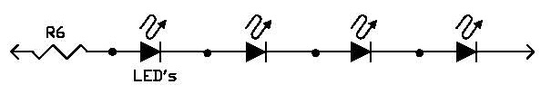
R7 Circuit
If you need three interior LEDs, here is the R7 circuit.
Brightness Current |
Resistor Value |
Mouser |
| 20mA |
180 ohm, 1/4W |
660-MF1/4DCT52R1800F |
15mA |
220 ohm, 1/4W |
660-CF1/4CT52R221J |
|
10mA |
330 ohm, 1/4W |
660-CF1/4CT52A331J |
5mA |
680 ohm, 1/4W |
660-MFS1/4DCT52R6800 |
3mA |
1.1K ohm, 1/4W |
660-CF1/4CT52R112J |
2mA |
1.6K ohm, 1/4W |
660-CF1/4CT52R162J |
R7 Table
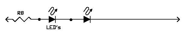
R8 Circuit
If you have two marker lamps, you might use this circuit. Note that if you need two LEDs, I recommend using the series combinations rather than the parallel pairs, as they will use less current. If you are using a capacitor, this means that the LEDs will remain lit longer due to discontinuities in picking up track power.
Brightness Current |
Resistor Value |
Mouser |
|
20mA |
330 ohm, 1/2W |
660-MF1/2LCT52R331J |
15mA |
430 ohm, 1/4W |
660-CFS1/4CT52R431J |
| 10mA |
680 ohm, 1/4W |
660-MFS1/4DCT52R6800 |
5mA |
1.3K ohm, 1/4W |
660-MF1/4CCT52R1301F |
3mA |
2.2K ohm, 1/4W |
660-MFS1/4DCT52R2201 |
2mA |
3.3K ohm, 1/4W |
660-MF1/4CCT52R1332F |
R8 Table
R5 Circuit
Finally, if you need just one LED for say, a
drum head, use this circuit.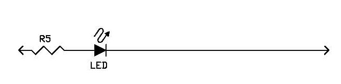
Brightness Current |
Resistor Value |
Mouser |
| 20mA |
510 ohm, 1/4W |
660-MF1/4LCT52R511J |
15mA |
680 ohm, 1/4W |
660-MFS1/4DCT52R6800 |
| 10mA |
1K ohm, 1/4W |
71-RN60D-F-1.0K |
5mA |
2K ohm, 1/4W |
71-RN65D-F-2.0k |
3mA |
3.3K ohm, 1/4W |
660-MF1/4CCT52R1332F |
2mA |
5.1K ohm, 1/4W |
660-MF1/4LCT52R512J |
R5 Table
![]()
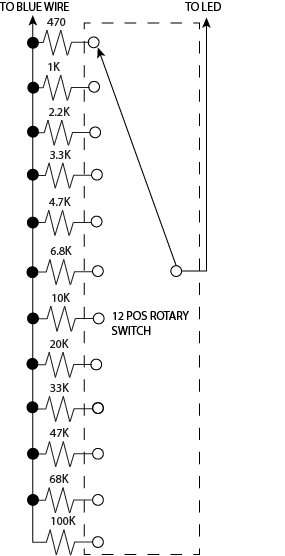
Resistor Substitution Box
A resistor substitution box allows easily to select from a range of resistors allowing you to easily figure out which resistor value is good for you.
Below are several commercially available units. You can make a basic unit for dimming LEDs yourself by clicking here.
Jameco sells one, p/n 2325599. It was $119.95 at the time of this writing (9/22/23). Really, this box is nice, but it has more capability than you really need for adjusting LED brightness. You do not need every possible value of resistance for adjusting brightness. Less expensive ones are made by Elenco.
Elenco makes several low-cost resistor substitution box kits.
Elenco doesn't sell direct. So click on the links below, search for "Elenco resistor substitution box", or buy one from Amazon. Spoiler alert: Amazon isn't necessarily the cheapest.
Model K37 This kit is about $15. It does not include a soldering iron.

Model K-37SLD This kit is about $17. It includes a low-cost soldering iron and solder.
Model RS-500 This box costs about $27. You can select any value from 1 to 10,000,000 ohms. While you can select any value, it is slower to flip all the switches than rotate the knobs of the K-37 model. Most importantly, if you don't keep a minimum of resistance selected, you could easily blow your LED.
For the average person, the K-37 or K-37SLD will do the job you need. The RS-500 is for the advanced electronics hobbyist or for someone who is really particular about selecting your LED intensity. Just beware that if you are particular, you will have to buy multiple resistors to achieve the value you have determined because not all values are manufactured.
| Dimming LEDs - selecting an appropriate resistor. |
| LED Strip Lights |
Copyright by Allan Gartner 1996 - 2023 © All rights reserved. You may print this for your own, personal, non-commercial use. Non-commercial, non-personal reproduction may be requested by visiting www.WiringForDCC.com/writeme.htm . All users, commercial and non-commercial, may link only to this site at www.WiringForDCC.com. Thanks to all who contribute to this site and the Q&A forum! |