|
||||
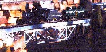
Decoder and Soundtraxx Sierra Sound Installation into a LGB C&S
Mogul My Colorodo and Southern makes it's rounds on my Finchfield & Wrensylvania That bear trap sure makes this locomotive look good, doesn't it? Unfortunately, due to the vintage of the sound system it comes with, this locomotive sounds so bad, I'm almost embarrassed to bring this locomotive out. No problem. Through the wonders of electronics, you can easily upgrade this first class locomotive to also include a first class sound system and DCC. I am able to maintain all of the C&S Mogul's great features, like the throttle sensitive flickering firebox. Betcha never noticed it flashes faster as the train's speed increases! You can keep your smoke generator, too. The schematic may look more complex than any other I have produced, but it really isn't. This locomotive installation is no harder than any other and here's why. Since the locomotive has existing electronics and circuit boards, as well as, a connector between the locomotive and tender, I have capitalized on all of this. The two additional sections in my schematic that are in the middle, simply show you where to tap into the circuit boards in the locomotive as well as the tender to use these things - especially the connector between the tender and locomotive. That's it. It took me a bunch of time to figure all this out, but when I was done doing all the figuring, it only took me two evenings to do the actual installation.
Things It Would Be a Good Idea to Know Before You Started As always, this installation note assumes you have read the section on Wiring Specific Locomotives. This write-up builds upon the information in the Generic G Decoder and Sierra Sound Installation write-up. Nothing in it is a waste of your time - it was based on installations in LGB locomotives! You will not be able to complete the installation without reading the generic write-up.
Openning Locomotives It can be a real project to figure out how to open a G-scale locomotive. It can be just as bad trying to close it back up! I highly recommend you video tape the disassembly! Remove some of the fake copper colored plastic plumbing. I damaged some of mine.
Decoder Selection This generic installation instructions can be used with any decoder made by any manufacturer of your choosing. See Decoder Selection in the DCC in the Garden section.
Wiring The colors of the wires that come out of the decoder on my schematic are the NMRA standard colors. The pin numbers are for the Zimo decoder. Note, I do not show the wires going to the ribbon cable connector on the drawing. I did this simply because things would be too cramped making the drawing too difficult to read. I have drawn a Zimo decoder which does not have NMRA colored wires. So for the motor and power pick up, I have shown the screw terminal block that the Zimo MX65S has. The wires shown with the numbers are the numbers of the wires on the ribbon cable connector that the Zimo has. With the cab light wired to ribbon cable wire #13, function F3 on your throttle will operate your cab light. Be careful! LGB evidently only owns a couple of different colors of wire, of which brown an black in particular get heavy use. Therefore there are many wires that are brown, black, green, white, and red. Make sure you are referencing the colors I mention. More importantly, make sure they come from the places I indicate! Wether you use the NMRA colors is up to you. How important is your sanity to you? I used a little Radio Shack board to hold the power supply circuit and filter circuit. See the section on Getting Electronic Parts.
You will connect the flickering firebox through a bridge rectifier, Z2. This is because I measured a voltage drop between the LGB firebox circuit and power pick-ups. While you may not absolutely need this, I wasn't willing to risk smoking my locomotive in the interest of science! Z2 is a bridge rectifier just like Z1. Z1, as well as the other components, are covered in the Generic G Decoder and Sierra Sound Installation write-up. If you haven't read it yet, face it, it's required reading! See the section on Getting Electronic Parts. You will be loosing the use of the built-in synchronized chuff. This
was a somewhat hard decision. Here was my reasoning: Cut the wires from the chuff sensor. These three wires go to the connector in the red socket on the main locomotive circuit board. From the connector in this socket, connect the motor leads from the DCC decoder, the bridge rectifier Z2 for the LGB flickering firebox circuit. Attach the blue wire from the DCC decoder for the rear tender light. Make sure you use the view of the main circuit board showing the board from the top. Flip the main circuit board over. Note that there are two sets of three wires coming from the tender. You will be working on the set of three closest to the tender. Note also the one that I have circled on my diagram. Make sure you use the view of the main circuit board showing the board from the bottom. Either remove the wire and connect it to the yellow wire from the decoder for the rear tender light, or cut the trace so that there is no electrical connection to the circuit board any more. Confirm that you no longer have an electrical connection to the main circuit board through the trace you just cut. Now solder the wire to this pad on the circuit board as a convienent terminal point. Leave the wire from the tender attached to this terminal point! Remove the huge, has to be more expensive than a Sierra, sound module from the tender. Either throw it away or give it to a less fortunate friend who is just getting into G scale who may not be able to afford a Sierra and definitely not an LGB - let alone both! Be sure not to snicker when doing this. You, like I, were probably at that same point earlier in life. They will probably be very happy to have it. After they leave, then you can snicker if you must. One last note. Don't let them hear it before you offer it to them. They may not take it! (I'm sure LGB isn't too upset. The sound systems that came before it were equal magnitudes of worse! In the course of electronic steam train sound history, it was a good stepping stone.) Owners of non-DCC command control systems: You can definitely use this circuit for your command control system. However, at a minimum, the color codings will be different.
|
Copyright by Allan Gartner 1996 - 2006 © All rights reserved. You may print this for your own, personal, non-commercial use. Non-commercial, non-personal reproduction may be requested by visiting www.WiringForDCC.com/writeme.htm . All users, commercial and non-commercial, may link only to this site at www.WiringForDCC.com. Thanks to all who contribute to this site and the Q&A forum! |