First Looks
NCE Products with Features that Caught My Attention


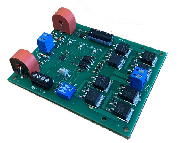
NCE AR10
Auto Reverser and Circuit Breaker
Brief Description
The AR10 is a combination auto reverser and circuit breaker. Trip current can be set from 1 to 10 amps. Includes status indicators for short detection and auto reverser polarity. Connection only requires four wires attached with screw terminals. An external short indication LED and manual reset button can also be added.
The AR10 can be used with any DCC system.
My Experience
The first good experience with any NCE product is the clear, concise, and easy to read instructions. It always answers my potential questions without having to contact their technical support or perform experiments before using their product.
Use with Frog Juicers
The section of my layout that requires auto reversing has a number of turnouts within it. I make extensive use of Tam Valley Depot Frog Juicers. Frog Juicers draw a small amount of current, sense when there is a short on a turnout frog, and reverses the polarity of the frog when needed. I was cautiously optimistic that I could get the Frog Juicers to work the AR10. I was prepared to work with some of the AR10's advanced features, if needed, to get them to work together. As it turned out, no problem! It worked fine just setting the trip current dip switches on the AR10.
My booster feeding the AR10 is a 5 amp system. Per the AR10 instructions, I set the trip current to 4 amps. This is easily done with the AR10's dip switches. I was hoping that if I set the AR10 trip current higher than the trip current of the Frog Juicers that things would work and they did.
If you are using a low current entry level system that can only supply about 2 amps, the AR10 will work set at 1 amp, but I would not expect it to work with Frog Juicers since you would not be able to set the AR10 trip current above that for the Frog Juicer.
Other Useful Information
As delivered, the AR10 comes set for 1 amp. So it should work with their Power Cab right out of the box. For higher powered system, you will probably only need to set the trip current via the AR10's dip switches.
NCE has informed met that the AR10 can be set to 1, 2, or 3 amps when used with a Power Cab as the Power Cab has some energy storage capability.
The AR10 has three LEDs - "Short", "Normal", and "Reverse". Don't get hung up if the "Reverse" light is lit most of the time. "Normal" and "Reverse" are just labels. They could have just as easily been labeled "Thisaway" and "Thataway." As long as the "Short" LED isn't lit, indicating an overload short in your reverse section, you should be happy.
No soldering is required. Everything is a screw connection.
Less sophisticated auto reversers have trouble with sound equipped locomotives. So far, it worked with the one sound locomotive I tested. In the coming weeks when I finish wiring my mainline and can run trains, I will try it out with other sound locomotives.
You can fine tune the AR10 to delay its response time, how long it is shut down, and how it restarts. You can look at the restart as a type of soft start. All these things are programmable through CVs. Everything worked for me without having to change any of these. If you make a mistake and want to start over, there is a factory reset you can do.
If you choose, once a short is encountered, you can disable automatic reset and require a manual reset with a push button. Don't give yourself a headache muling over the pros and cons for doing this. From the factory, the AR10 comes with automatic reset enabled. I have left mine set up for automatic reset.
Finally, if you want a remote indication of a short on a control panel, the AR10 has a provision for this as well.
Enjoy! You will have this up and running in no time!
NCE EB1 v1.1
Electronic Circuit Breaker
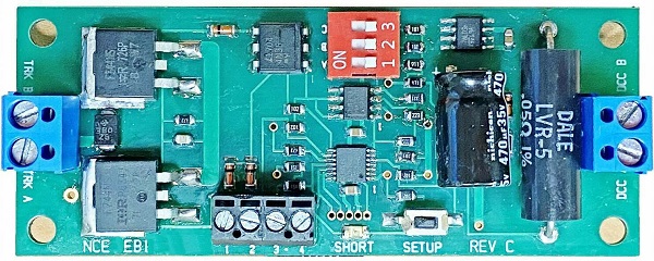
1.25" x 3.75"
The new v1.1 EB1 replaced the jumper pins with a DIP switch to set trip points and a button for set up.
Improvements Over Original Version and Brief Description
There are a number of noteable improvements for this new version of the EB1. One game changer is that the lowest trip point is lower than the old version. It is now 1.5 amp(A); making it suitable for lower power entry level systems. I also noted that the jumper pins, and the sometimes tough to handle and see shorting plugs, have been replaced with DIP switches (in red above) and a set up push button.
The new EB1 is the same size as the original EB1. So it is still much smaller than some other electronic circuit breakers on the market.
No soldering is required. Hook-up is easy with just four wires - two to the booster and two to the track.
It remains capable of handling up to 10 A.
In addition to the lowest trip point going down, the other trip points have changed somewhat. This is not important. Just pick a limit that isn't too low for your locomotives and lower than your booster trip point. I have a 5 A booster and have chosen 3.3 A for the EB1 trip point for my layout.
It can be used with any DCC system.
My Experience
The first good experience with any NCE product is the clear, concise, and easy to read instructions. It always answers my potential questions without having to contact their technical support or perform experiments before using their product.
The instructions say that when you screw it down, not to get it too tight or else the board may bend and crack some components. That's good advice. Just barely snug it down. For insurance in my layout room that isn't always heated and cooled, I snug down and then back off the screw just a tiny bit.
Use With Frog Juicers
Another consideration for setting a trip point for me is that I am using Frog Juicers from Tam Valley Depot. They are designed to trip about 2 A. It was important to me that the Frog Juicers and EB1 work together. With the EB1 set to 3.3 A, everything worked fine.
Other Useful Information
It has a status LED indicating everything is good or if the EB1 has tripped. An external LED for a control panel status can be added. Also, if you want a manual reset, you can do that, too.
The advanced user can change the response time, the shutdown time, and the soft restart "custom startup" as well as give it an accessory address.
NCE Switch8-Mk2 & Button Board
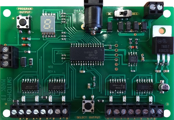
Older Switch8_MK2.
Newer version has two connectors on the left side. The second connector is not currently used.
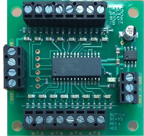
Button Board
Overview of Features
NCE has several products for turnout control using DCC. The Switch8-Mk2 is designed for controlling Circuitron Tortoises and other stall motor type switch machines that draw less than 40mA. Since Tortoises usually draw less than 20mA, you can drive two Tortoises in a crossover on one Switch8-Mk2 output.
The Switch8-Mk2 can drive up to eight 40mA switch machines. If you don't need 8 outputs, the NCE SwitchIt Mk2 can control two Tortoises.
The Button Board is designed as an extension of the Switch8-Mk2. It is not a stand-alone product. It adds the ability to use buttons or toggle switches to operate the switch machines attached to the Switch8-Mk2. Once wired together, think of them as one unit.
You don't have to have a Button Board or even a control panel. The Switch8-Mk2 can be accessed with your throttle (SEL ACCY button on NCE throttles) or JMRI and smart phone apps.
NCE accessory decoders, like the Switch8-Mk2 and the Button Board, can be used with other DCC systems that support accessory decoders.
Powering the Switch8-Mk2 (and Button Board if used)
The Switch8-Mk2 has the ability to add an external power supply. Note that it is not intended to be used standalone and needs to be attached to DCC track power. You will probably only be worried about drawing a lot of track power if you have a lot of Switch8-Mk2's and Button Boards or you have a entry level system that only provides a couple of amps of track power.
Connecting the Button Board to the Switch8-Mk2
It only takes three wires to attach the Button Board to the Switch8-Mk2. There are a couple of things to watch for. One, my Switch8-Mk2 has two three-screw connectors. One is for the future Relay Board. The other is for the Button Board. The Switch8-Mk2 is clearly labeled. Two, the three screws on the Button Board are not in the same order as on the Switch8-Mk2. When wired, they cross. Again, both boards are clearly labeled for GND, +, DATA. Now that I have given you a heads-up on these, you will be paying attention. You won't have any trouble hooking them up.
Programming the Switch8-Mk2
Note, while there are instructions for programming features of the Switch8-Mk2 in the Button Board instructions, there is more detail in the Switch8-Mk2 instructions. Look to the Switch8-Mk2 instructions whenever programming.
The Switch8-Mk2 comes with it's outputs programmed for accessory addresses 1 through 8. This is easily changed to any DCC accessory address.
If you hook up a switch machine and it throws in reverse of what you intended, you can just swap the wires on the Switch8-Mk2. You can also program the Switch8-Mk2 to reverse that output. The choice is yours.
You can use a typical toggle switch, a momentary contact toggle switch, or push buttons. Momentary switches allow you to control a single switch machine from several control panels.
You can also use a single pushbutton to control a turnout. You just put the Switch8-Mk2 in toggle mode. Every time you press a given button the switch points will flip. I'm a minimalist when it comes to control panels; mainly because I have spent countless hours wiring club control panels with dazzling indicator lights. For what? If you can see the turnout, you will probably look at the switch points to make sure they have flipped the way you wanted. (You can wire a turnout to provide position feedback, but most people don't wire their turnouts that way. More wiring and more cost! However, if you are planning on signaling, this is something you might want to do.)
There are two inputs on the Button Board for each turnout. When using the toggle mode, which input provides the toggle feature? Maybe both? I couldn't resist. I had to find out. As it turns out, either input will toggle the associated turnout.
Another cool feature is that you can program the Switch8-Mk2 to ignore the Button Board. If you are having an open house for the public, you can effectively kill your control panels to keep little hands from crashing trains. Turnouts can still be thrown by the dispatcher or anyone with a throttle equipped to do so.
NCE Light-It
Universal Lighting and Signal Decoder
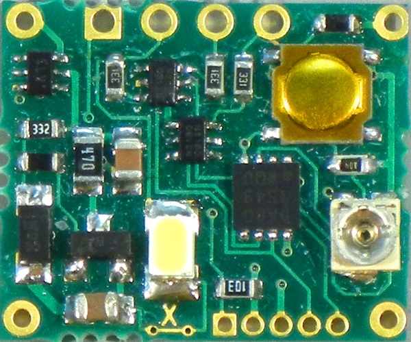
Light-It
Actual size: 15 x 18 x 5 mm (0.59 x 0.71 x 0.02 inches)
Overview
The Light-It is very versatile lighting decoder that is well thought out and is well-suited to all its possible uses. There is a lot to be said about this little device. Besides illuminating cars and structures, it is can drive the lighting of a crossing signal and of-course, signals. To avoid flicker when illuminating a passenger car or caboose, it even has a provision for a keep-alive capacitor.
It is useable with any DCC system. However, not all DCC systems can access the Light-It in all its ways (for example: Some systems do not support signal addressing.)
Software wise, the Light-It is identical to the Illuminator. So you can easily use either product without having to learn two different command structures.
Both the Light-It and Illuminator have fifteen lighting effects that can be used when addressed as a locomotive or accessory modes. In signal mode, the three outputs produce the signal aspects as listed in the NCE instructions.
Applications
- Signaling
- Lighted passenger cars and cabooses
- Structures (Also consider the Illuminator for this application. See below.)
- Remote indicators, like control panel status lights.
Features
It looks big here, but in actuality it is just a little bigger than a dime. This is so that you can put it inside HO passenger cars, cabooses, or structures needing illumination in most scales.
If you are illuminating a structure, passenger car or caboose, it comes with a built-in white LED. This can be disabled by cutting the trace under the X in the photo above.
It can drive each output up to 10mA and already contains the required series current-limiting resistor. You change the brightness of each LED output by setting CVs. (Note: It cannot be used with incadesent light bulbs.)
Addressing
It is flexible in how it is addressed. You can assign it a locomotive address and control it with locomotive functions. You can make the lights flicker, too! Each LED is individually controllable.
You can also control it as an accessory decoder. This is another way you might want to light your cars, if you don't want to have to select them as a locomotive. Accessing it as an accessory decoder is how you might want to illuminate buildings. You can even mimic failing flourescent lights or mercury vapor lights with their slow turn-on.
Finally, you can address it as a signal. Normally, you would use the NCE Mini-Panel or JMRI. NCE throttles also allow you to address it by pressing SHIFT and CLEAR buttons simultaneously. If this doesn't sound as convenient as most NCE throttle commands, don't worry. You probably will only use this for testing a signal. You don't want operators changing signals themselves during an operating session!
Wiring it Up
To keep it small, you will have to solder all connections to the Light-It. I suggest the following tools to make soldering to it painless.
- a magnifying light
- a 15 watt soldering iron with a pointed tip
- a third hand
- 0.031" diameter rosin-core solder
- thermal wire stripper. Especially useful on very small diameter wires. These are expensive. Get a used one on eBay.
My initial use is for signals. I plan on lighting a caboose. Stay tuned for an update here when I do.
Besides signals, you can light a structure or a passenger car. You can have up to 3 LEDs controlled by a single Light-It. (You can put a few LEDs in series if they are high effeciency.) This would allow you to light a sleeper passenger car and individually light and control the sleeper cabins. Also, you could light and control different sections of structures. Finally, you can light a grade crossing signal. For rolling stock, you can add keep-alive super capacitors. As you can see, the Light-It is extremely flexible!
Trying it Out
Due to it's flexibility, I suggest you take small steps; especially with your first Light-It and if you are planning to use it for signaling. If you are like me, I never worked with DCC signal commands before. Have no fear. I took those small steps and everything worked just fine.
1. Hook up the Light-It to track power. It comes set up as locomotive address 3. So select locomotive address 3 on your throttle and turn on the headlight (function 0). The on-board Light-It LED will light.
2. Disconnect from track power. Hook up LEDs, in my case, signal head, to the yellow and red output. If you are using white LEDs to light a passenger car or structure, that's fine. Hook up to track power and select functions 1 and 2. The yellow and red LED outputs will light.
3. Disconnect from track power. If you want to control a third external LED or a green signal, cut the run on the Light-It marked with the "X". Wire up the green or third LED. Hook up to track power and select function 0 on your throttle.
At this point, you know your Light-It is working.
4. If you need to change the brightness of your different LEDs, now is a good time to do that. Also, if you need to add any special effects, like a flickering flourescent, now is a good time for that, too.
If you will be using accessory addresses to operate your Light-It, follow the instructions and test it.
I am using my first Light-It as a signal controller. So I programmed in address 1000 for signals as outlined in the instructions. You can use whatever valid signal address you wish.
5. Test out your Light-It for accessories or signals as you desire.
6. If you are using Light-It in a passenger car or caboose, you might want to add keep-alive capacitors. NCE sells those, too. I always recommend you hook up keep-alive capacitors as the last thing you do. If you don't, you will find yourself waiting for them to discharge at each of the above steps.
Enjoy your Light-It!
NCE Mini-Panel
Automation Controller for NCE DCC Systems
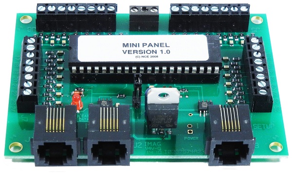
Mini-Panel
Overview
The Mini-Panel is a simple, yet powerful, automation controller for use with NCE DCC systems. It's most common use may be to flip several turnouts with a single button press. You can also do simple layout automation and simple signal control. Do all this without tying up a computer and having to start it up each time nor having to learn JMRI.
Documentation
The Mini-Panel comes with a set of instructions that describe how to hook it up and use it. It includes some examples of the commands. I think NCE instructions are easier to understand than some other manufacturers'.
On page 9 is a "menu navigation chart" which shows all the commands and how to get to them. Without seeing it, this may sound scary, but it isn't. There are not that many commands and it all fits on one page. You will find this page handy. It is a great summary of what you can do with the Mini-Panel.
Don't stop here. If you want to do more than just control turnouts, contact NCE's tech support. If all you want to do is control turnouts, the instructions that come with the Mini-Panel are all you need. But if you want to do more, NCE can send you a number of examples, including wiring diagrams, and the Technical Reference manual for the Mini-Panel. Note: The URL in the instructions takes you to the wrong NCE Corp. Use: https://www.ncedcc.com/
Entering Programming Mode
There is one thing that isn't in the instructions that come with the Mini-Panel. It is how to get it into programming mode. It is in the Technical Reference manual. All you need to do is place the little programming jumper on the prog pins. Then power up the Mini-Panel. Then you will see the Mini-Panel startup screen appear on your throttle. Once this happens, remove the programming jumper.
Turnout Control
The simplest thing you can use your Mini-Panel for is turnout control. The instructions that come with the Mini-Panel are likely all you need. You probably don't need to contact NCE for Technical Reference for the Mini-Panels or any of their automation examples.
You don't need to be a programmer for turnout control. It is pretty much a list of the turnouts you want throw. The Mini-Panel can easily control four turnouts for each input.
You can do more. You just have to trade inputs for more turnouts. For example, if you wanted to control up to 7 turnouts, you would use the Mini-Panel LINK command. Be aware that doing this consumes another input. This means for every LINK command, you may not be able to use that input for a normal input.
You can also activate NCE macros to avoid using up Mini-Panel memory associated with other inputs.
Imputs and Event Trigger
The Mini-Panel has 30 inputs and 1 master reset input. An input is activated whenever a switch or something like a BD20 block detector takes the input from a logic high to a logic low. Switches do this whenever they are tied to the Mini-Panel ground terminals. A BD20 does this as well.
If you intend to use push buttons to control a ladder, you probably don't need to read the rest of this section on inputs and event triggers.
Now, to avoid unexpected results, reread the italicized text above. If an input to the Mini-Panel is already low when you power up your layout, it won't see the high to low event and won't do anything. There may be other situations where the high to low event won't be seen. Just be cognizant of this in case you have weird things happening.
Why do event triggering? A lot of control systems are designed to work this way. It avoids other problems. No system is perfect.
Note also that when a block clears, you get a low to high transition from a BD20. The Mini-Panel does not react to low to high's. Remember; only high to lows. Have no fear, there is a simple solution to allow the Mini-Panel to react to low to highs. In the documentation that NCE can send you, is a one transistor circuit for converting a clearing block situation to a high to low that the Mini-Panel reacts to. I have heard of people using relays instead of the transistor. The transistor is much cheaper. You may need someone to show you how to hook up the transistor.
I intend to use my Mini-Panel to control signals and I may have a need for the transistor. If I do, I'll post information on hooking it up on this webste.
Simple Layout Automation
The NCE Technical Reference information and accompanying examples, can give you some ideas on simple automation. With a little creativity, you can do a lot. You also should be able to make a passenger train stop at stations - great for a public display in a museum.
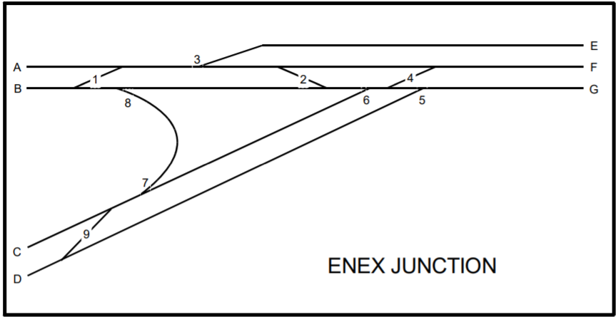
Example of N-X turnout control using the Mini-Panel
When the Mini-Panel detects that one of the buttons (A-G) is pushed it starts scanning for the press of any second button that results in a valid route through the junction. For example A and B pressed at the same time is not valid by B and F is a valid route. When a valid route is detected the panel issues the proper commands to align the appropriate turnouts for the route.
The Mini-Panel is simple, but to do a litle layout automation, you may need some basic programming skills. Setting up a Mini-Panel might be a great place to see if you have a future in programming. Can you make a list of things in the order they need to occur? Can you make decisions that change the list of things that need to be done? (The Mini-Panel only has one decision instruction: SKIP.) Cna you step through a sequnce of things to do in the order they must occur? If you can, you can set up your Mini-Panel. Get the NCE Technical Reference package and walk yourself through their automation examples. If it makes sense, you are on your way!
Signals
The Mini-Panel can do some simple signal control. I intend to use my Mini-Panel control signals using NCE's Light-It product described above. The nice thing about using a Mini-Panel instead of JMRI is that you don't have to have a computer tied to your layout and you won't have to worry about starting it up and running JRMI. For a club layout or a public display, this may be ideal.
Once I get my signaling going, I will post how I did it. Stay tuned.
NCE Illuminator
for Woodland Scenics Just Plug System and Other Uses
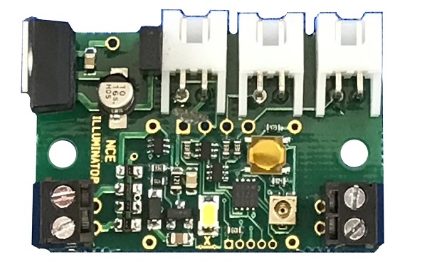
1.1"W x 1.6"L x 0.4"H
Leave a little room for the power wires and the connectors for the Woodland Scenics Just Plug system.
Overview
The Illuminator is primarily intended to be a DCC controller for the Woodland Scenics Just Plug™ lighting system. The Illuminator can be used with any DCC system; not just NCE. Not all systems, especially entry level systems, support all of the capabilities of the Illuminator.
Software wise, the Illuminator is identical to the NCE Light-It. So you can easily use either product without having to learn two different command structures.
Both the Light-It and Illuminator have fifteen lighting effects that can be used when addressed as a locomotive or accessory modes. In signal mode, the three outputs produce the signal aspects as listed in the NCE instructions.
Applications
- Structures. In particular, the Woodland Scenics Just Plug lighted products, but can easily be used with any structure.
- Signaling (Also consider the Light-It for this application. See above.)
- Lighted passenger cars and cabooses (Also consider the Light-It for this application. See above.)
- Remote indicators, like control panel status lights.
Features
For people who don't like to solder, power can be attached to the Illuminator using screw terminals. Also, the Illuminator comes with harness cables so that you can use it for your lighting applications even if you are not using the Just Plug system. So you can avoid all soldering if you want to.
Due primarily to the connectors, the Illuminator is bigger than the Light-It. Still, you might be able to get it inside your favorite ligthed passenger car. The dimensions are above.
There are a lot of cool features, so be sure to carefully read the instructions that come with it.
Resistors or Not
The Light-It has built-in resistors. The Illuminator does not. The primary reason for this is that the Woodland Scenic Just Plug products already have resistors built-in. You don't need them in both places. If you tried to use a Just Plug product with the Light-It, at best it will probably be too dim. So the Light-It is not recommended for Just Plug products.
On the flip side, if you are not using an Illuminator with a Just Plug product, you will need to add a resistor to each output. What value do you need? Start with 3.3k-ohm and work down until you achieve the desired brightness. An easy way to do this is to use a resistor substitution box that is described in my Using Miniature LEDs section of my website. For a small LED, you will probably end up with something around 2.2k-ohms or so. Make sure you note that the red wire coming out of the supplied connectors are negative and the black is positive.
Voltage and Current Differences
The Illuminator operates with a max output voltage of 12V for the Just Plug products and can output about 35mA per output. The Light-It operates with a max output voltage of 5V and can output about 10mA for red, green, or yellow LEDs or 5mA for white and blue LEDs. I have a couple of Woodland Scenic ready-made structures that are lit. The structures are rated for 30mA. They work just fine with the Illuminator. I even used some of the Illuminator's lighting effects on a Woodland Scenics structure.
With the Illuminator, you can use larger and brighter, higher current LEDs to light structures. You can also put several LEDs in series.
Addressing
Both the Light-It and the Illuminator can be used three ways; the functions of a locomotive, as an accessory, or a signal.
Use the locomotive mode when you want to to turn on or off each output individually by using the function keys on your throttle. Each output can have a different effect. The effects are configured with CVs. You can consist your Illuminator.
In the loco mode, you might use your Illuminator or Light-It in cars of a train. You can also light up a town.
Use the accessory mode when it is okay that all three outputs turn on or off at the same time. Of course, each can have a different effect. For example, the Mercury vapor effect may be activated right away, but the effect takes about 30 seconds to go full on. If you use the Illuminator or Light-It in a car, you can, but it won't be consisted with the locomotive. You can also use them to light up a town.
Two of the effects are for crossing gates. This is available in all mode, but I think its use makes the most sense in the accessory mode.
The last mode is the signal mode. As in all modes, you can use this mode creatively for whatever you have in mind, but it's obvious application is for signals. Not all systems, especially entry level systems, support signal commands. Either use one of the other modes or buy a new system!
